Week 3: 09/19: electronics production
Assignments
- group assignment: characterize the design rules for your PCB production process
- individual assignment:
- make an in-circuit programmer by milling the PCB
- check if you can program it
- then optionally try other PCB processes
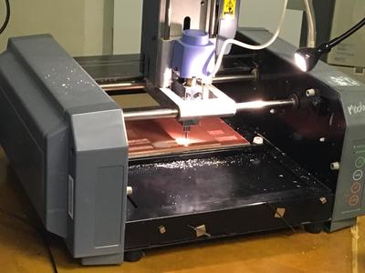
Tools used: milling machine: Roland Modela MDX40a, mods
File preparation
For the chip architecture, we could follow the instructions on Brian's page. Thanks for providing the instructions!
The first step to download the PNG files for the traces and the board outline:
Milling
Below are the notes I took for operating the milling machine. This process successfully led to a mill-breaking count of zero!
- Turn on Modela
- Add sacrificial layer
- Tape down the copper plate
- 1/64 for precision work - traces
- 1/32 for thicker layer - contours
- Desktop - stop mods server
- Desktop - start mods server
- Firefox - right click - programs - open server program - machines - Roland mill - MDX-20 - PCB
- Set home machine first: type 0,0 in 4th block
- Click on view mode to go to view mode
- Bring down the end-mill manually
- Grab hex tool - hold end-mill to make sure it’s not falling
- Move machine up to remove/release end mill
- Stick end mill to the magnet
- Take 1/64 and put it in the machine
- Move down (reference, use screws as reference: front view should cut the two screws in half)
- Adjust the end-mill holder with hex screw
- Tighten it exactly right - otherwise you break everything!
- Go to the first column - click select png file - open hatch file
- Upload Brian’s file
- Resolution dpi 999.998
- Second tab: click on mill traces (1/64)
- Second tab: click on mill outline (1/32)
- Third tab: Press calculate
- Inspect the visual of the path
- Every time you change the origin, you have to recalculate again
- Mill traces: Offset number = amount of lines, how many paths it’s going to run. Can also be used as rubout
- When done: send file in last tab
- Machine operates
- Vacuum the dust off the part when the machine is ready
- Grab tissue to fix the toughness of the thing
- Open cutout png file
- Move to origin
- Start again with taking out the end-mill
- Place it back in the tube and place it in the collection bin
- Mill again according to same steps
- Use tool to remove the object from board
- Remove tape
After the training, we started with the group assignment. The group members are: Eric, Tina, Ravi, Carol and Océane. To characterize the design rules for our own PCB production process, we downloaded the two files from the CBA website, which can be found here:
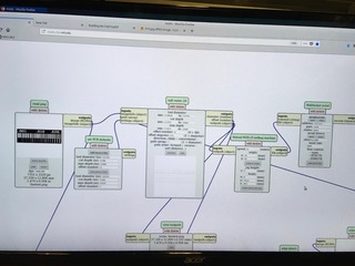
Next, we followed the workflow described in my notes, starting with importing the files in mods.
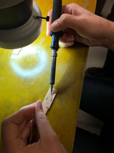
Then we installed the correct end-mill.
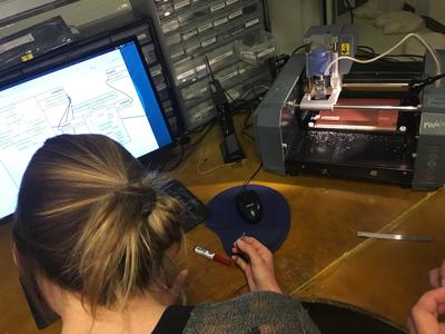
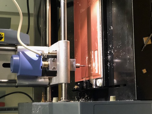
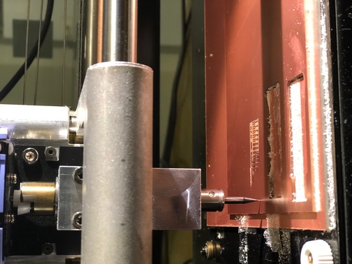
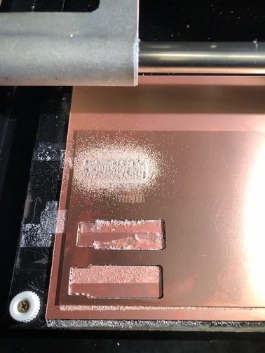
Magic moment, the milling process! Somehow I can't turn this image...
Vacuuming out the board.
Meh....
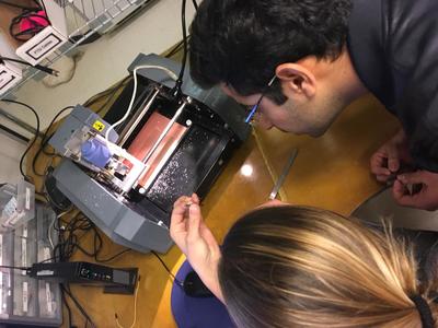
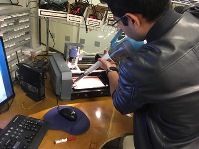
We were too careful the first time, so the end-mill didn't touch the copper plate. Apparently the board is slightly sloped, so a part of the copper plate was not milled. The problem could be solved by lowering the end-mill, and we checked if it touched the board this time by trying to slide a piece of paper underneath it.(apologies for the image)
The moment of truth..
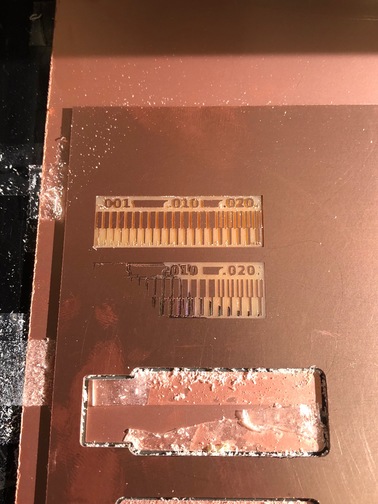
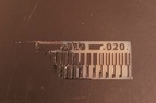
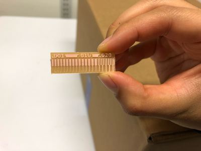
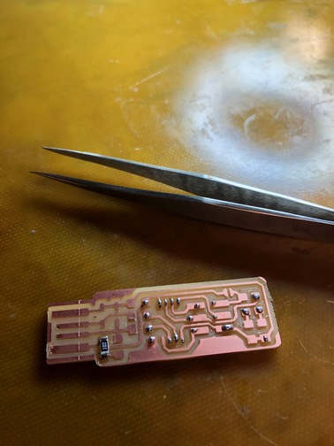
Success! This is the result of the group assignment!
Next, the same process was repeated to make the individual piece.
Soldering
The next step is to solder the components on the board. Below are my notes:
- Turn on the light
- Turn on air exhaust
- Study the two diagrams below: board layout and schematic
- Collect all parts
- Use tweezers to remove plastic from white strips 1k ohm
- Clean the soldering tip
- R1 first, grab solder
- Put some solder down, this is called tinning
- Resistors are not polarized. Capacitors usually are, but ones with a ceramic coating are not. If polarized, it’s important to pay attention to the direction of the orientation. The mircroprocessor has a little circle which helps to orient it. Otherwise it will burn.
- Place resistor on top of the solder.
- Melt solder, just enough to get it locked. This is called ‘anchoring’
- Solder the opposite side. More solder is used on this side to fix it properly
- Go back to first point to solder it down completely.
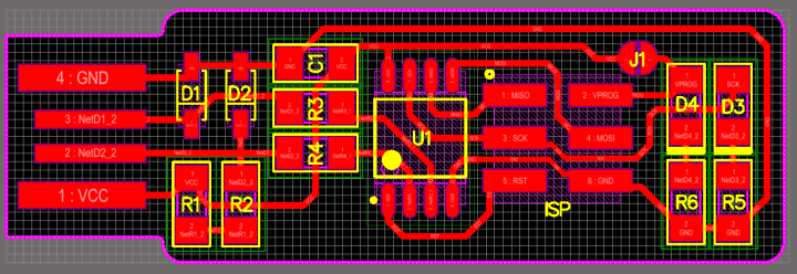
Board layout. Credits: Brian
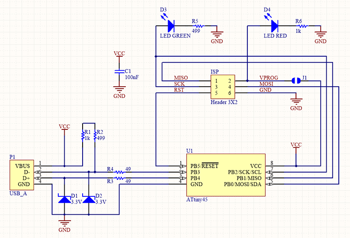
Schematic. Credits: Brian
Materials
1x ATtiny45
2x 1kΩ resistors
2x 499Ω resistors
2x 49.9Ω resistors
2x 3.3v zener diodes
1x red LED
1x green LED
1x 100nF capacitor
1x 2x3 pin header
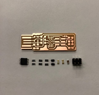
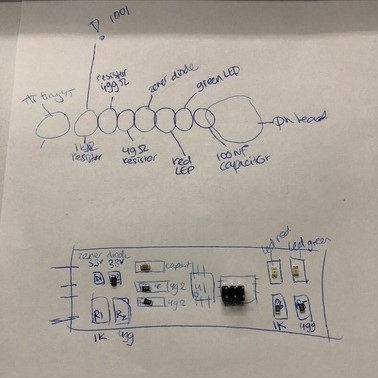
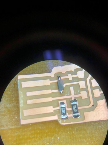
First I decided to lay out the components, and make sure that the directionality and locations are correct.
To practice with the soldering technique, I tried it on a sacrificial board. Technique:
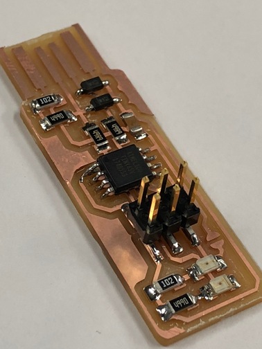
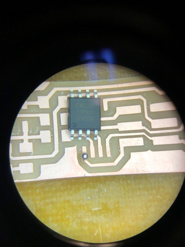
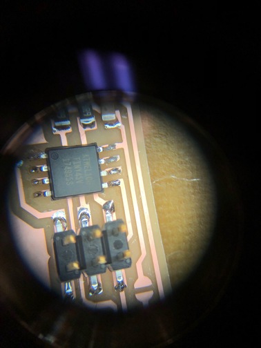
Close-up of the PCB through the microscope. This is the microcontroller, of which I soldered the bottom left first. That part definitely isn't as smooth as the rest.
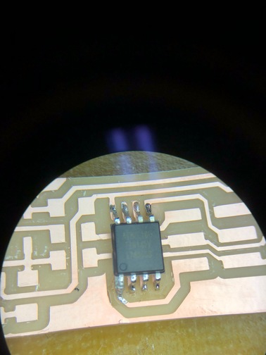
The next components were easier.
The final result!