Week 5: 10/03: electronics design
Assignments
- group assignment: use the test equipment in your lab to observe the operation of a microcontroller circuit board
- individual assignment:
- redraw the echo hello-world board,
- add (at least) a button and LED (with current-limiting resistor)
- check the design rules, make it, and test it
- extra credit: simulate its operation
- extra credit: render it
Tools used: Autodesk Eagle, Modela MDX-20, GIMP
Electronics design
The design is based on the file Neil provided.
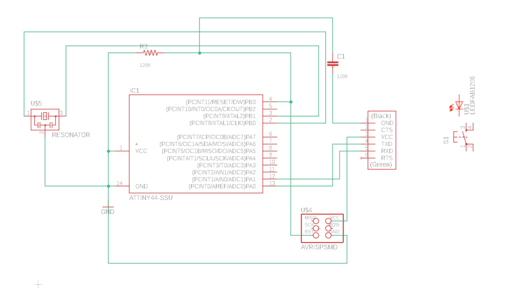
The initial schematic design. I spent days to figure out the program, and this is not the most useful way to draw a schematic.
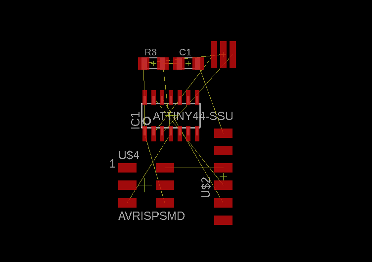
This is the ratsnest. I tried to autoroute it but that led to many errors.
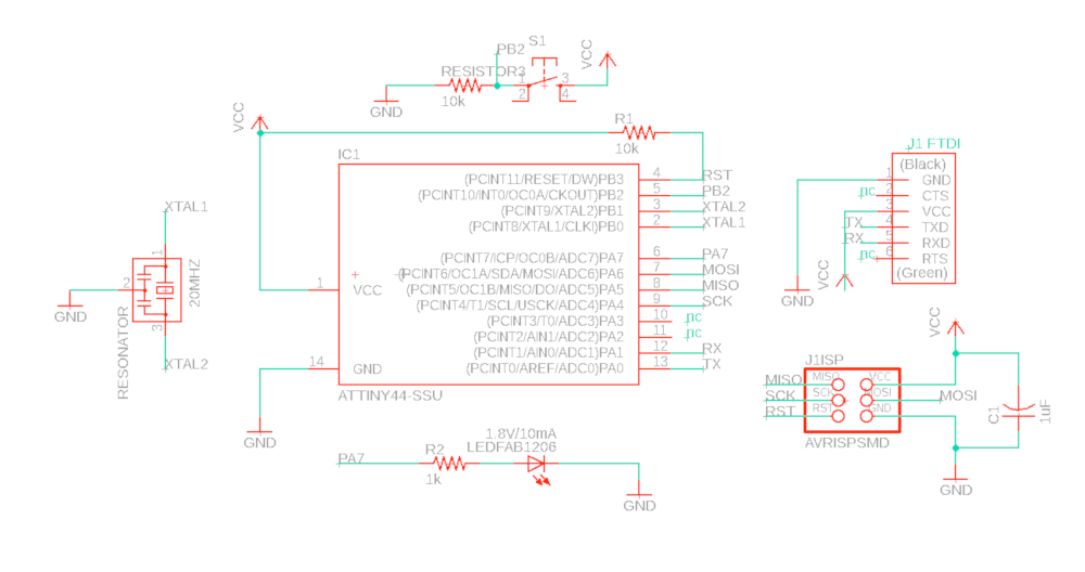
For improved clarity, the new schematic separates the elements.
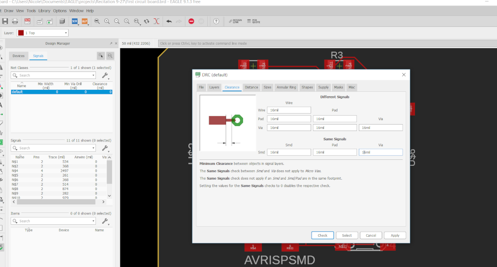
Before drawing the board, it is important to set the boundary conditions. In the ratsnest, go to Tools --> DRC --> and make sure to set all values in the Clearance tab on 16mil. On the Sizes tab, set the Minimum Width to 14mil. Lastly, go to the Supply tab and set Thermal Insulation to 16mil.
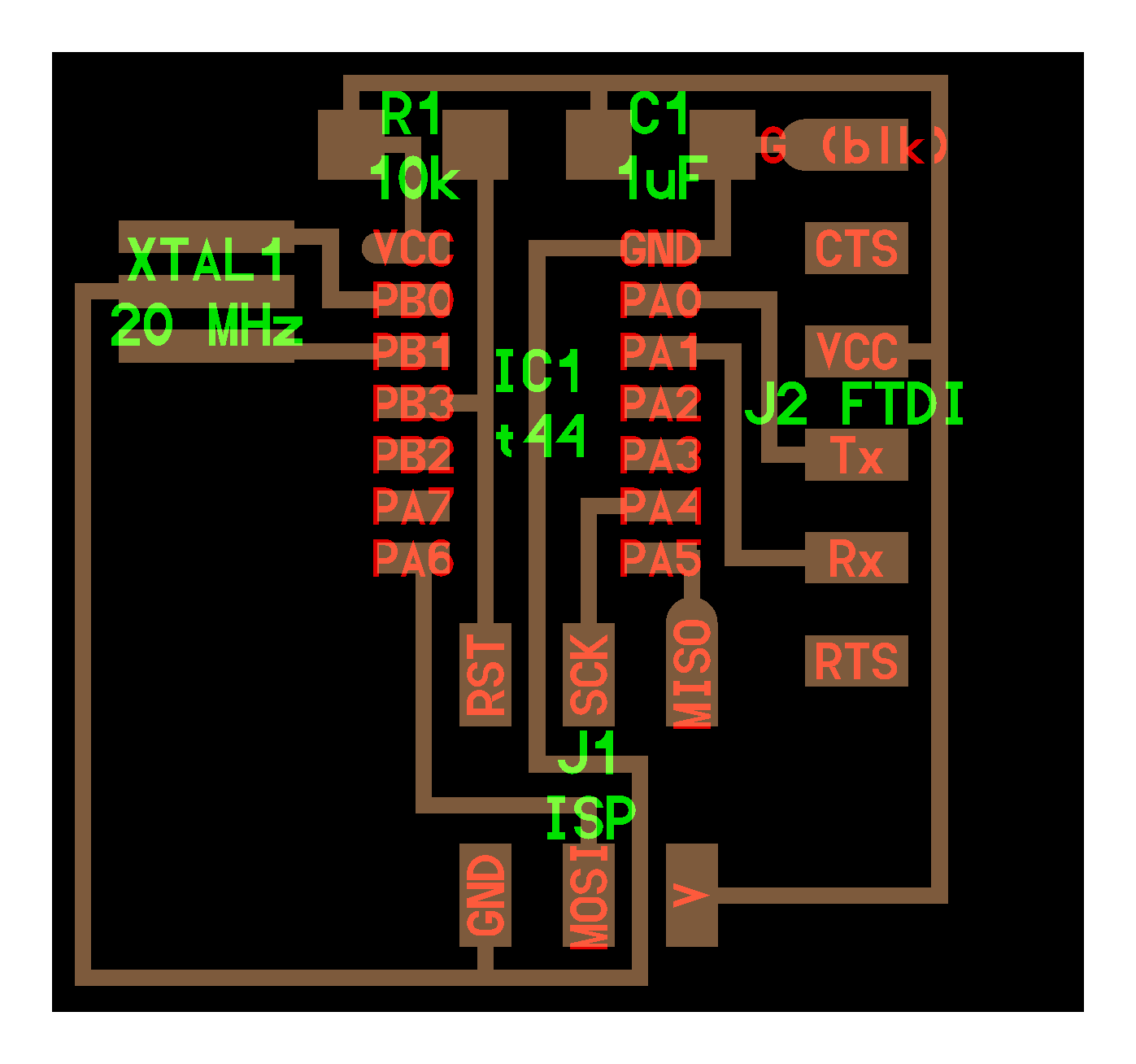
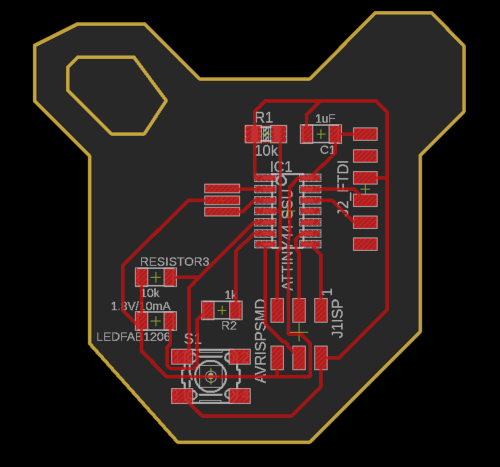
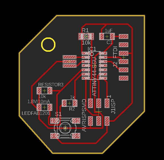
The result!
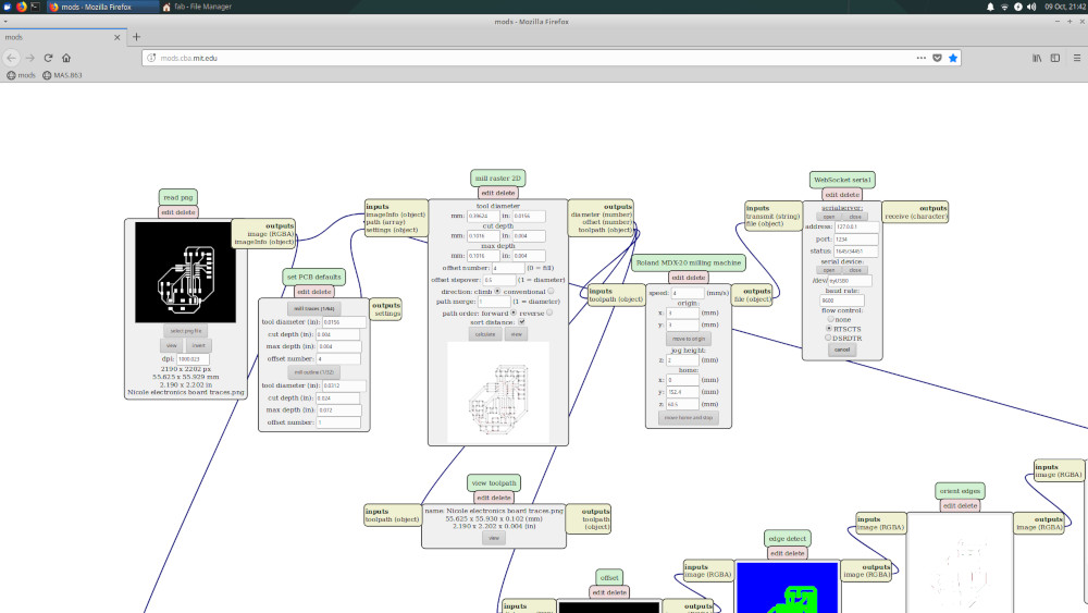
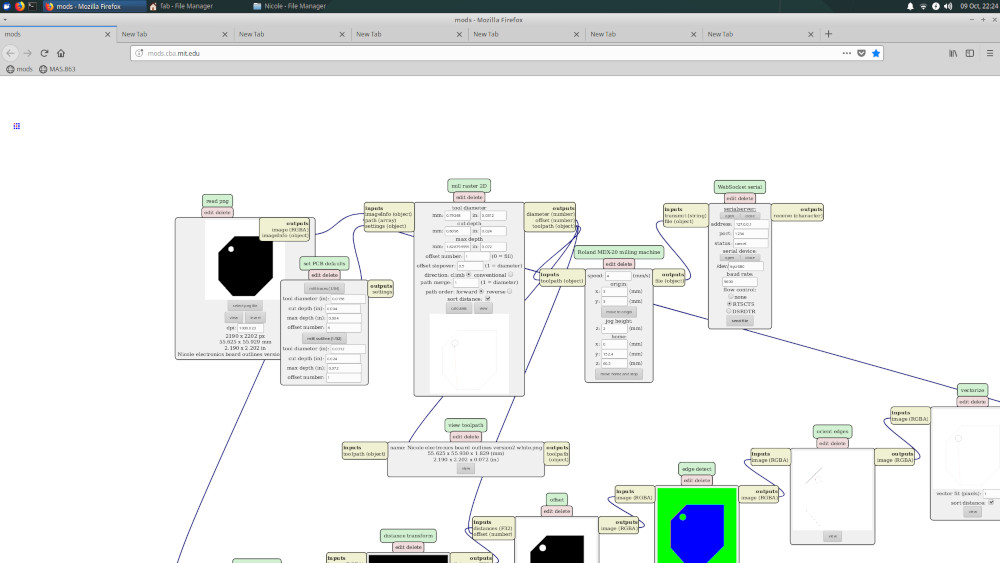
Import in Mods.
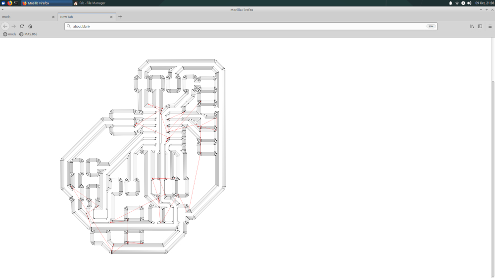
Check the path of the traces.
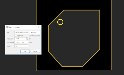
The outline of the bear turned out to be too large for the physical board, so I made a smaller outline. Settings: File --> export image. 1000 dpi. Monochrome
To remove the text for the png file: Go to top layer: Display 'Display none top' to remove the outlines Go to Dimension layer: 'display none dim' to remove the traces.
Import and settings in mods
Final result
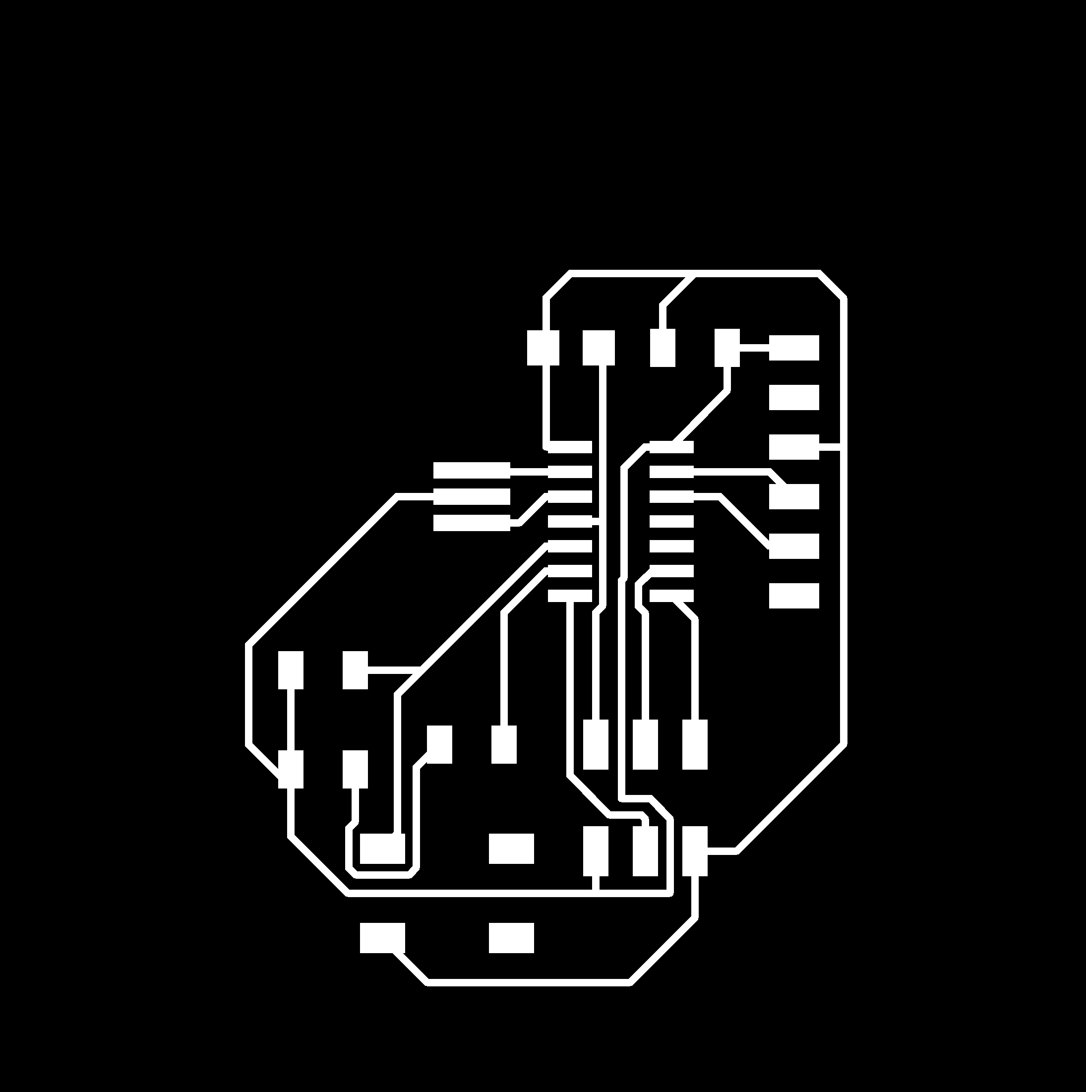

Before the outlines could be milled, the board should be filled with white space. Otherwise the milling machine will trace the outlines twice.


Downloads
- Download schematic in Eagle
- Download board in Eagle
- Download traces .png file 1000dpi
- Download outline 1 .png file 1000dpi
- Download outline 2 .png file 1000dpi
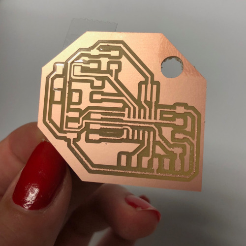
Milling
Before I could start milling, the sacrificial layer and the broken mill-end had to be replaced.
Home settings: x=3 y=3 Traces: 4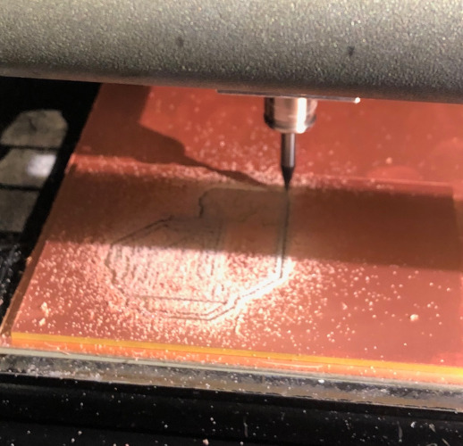
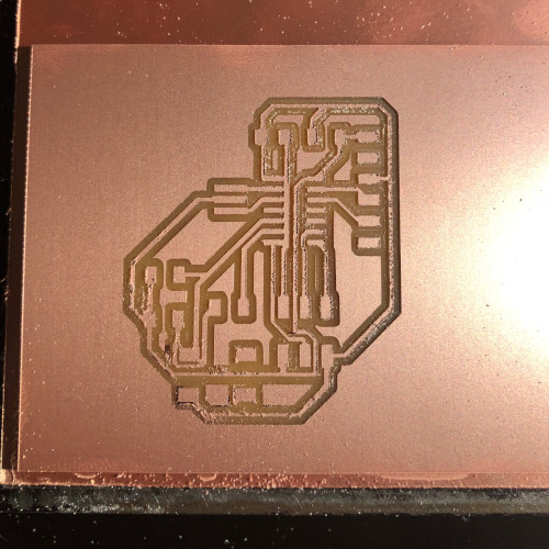
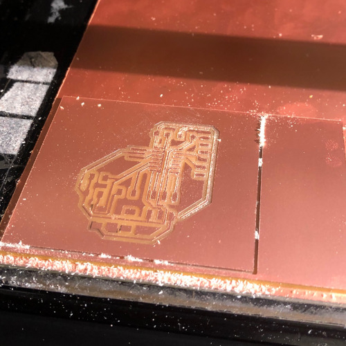
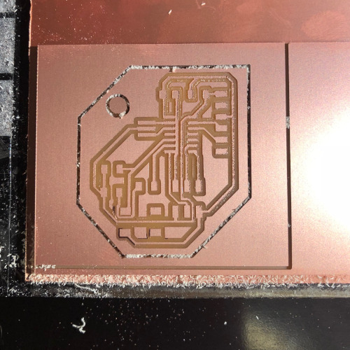
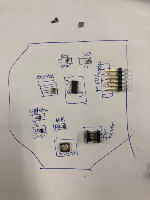
Soldering
1x ATtiny44
1x SMD button
1x 20MHz resonater
1x 6-pin FTDI header
1x 6-pin ISP header = SMD in reality
1x green SMD LED
2x 10k ohm resistor
1x 499 ohm resistor
1x 1uF capacitor
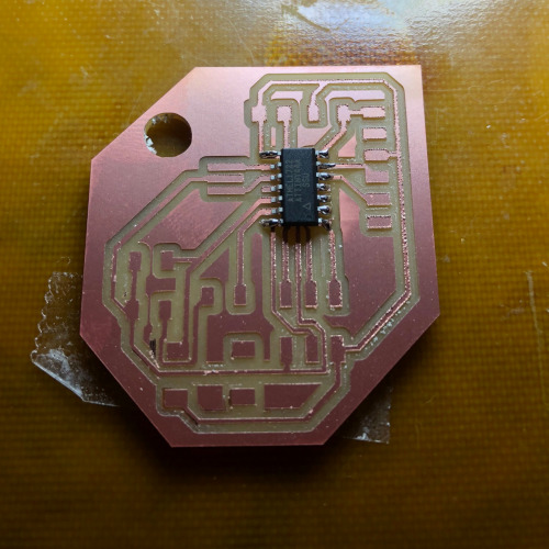
Sadly, I accidently soldered the microprocessor in the wrong direction.. Here are various attempts to desolder, unfortunately none of them led to success.
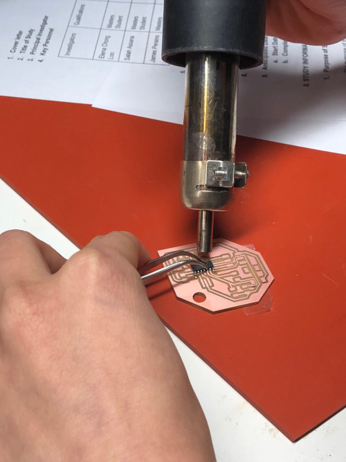
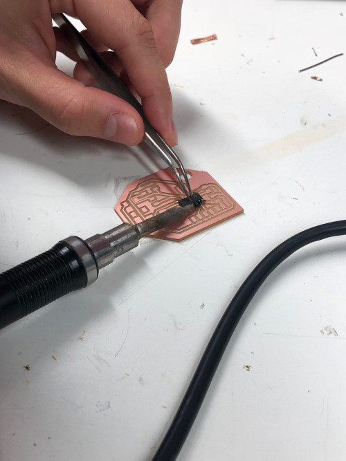
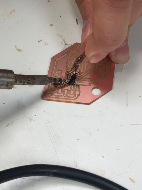
Desoldering troubleshooting
- The temperature sensor of the machine is not accurate
- The behavior of the heat gun is unpredictable
- Time to heat up is approximately 1 minute
- Set the machine to 350 for desoldering, now to 310
- Air pressure
- Turn off again: press hot air gun on again, wait until I w below 100 then press red button
Programming
