User Interface

For this week, I decided to make a two button controller 2d interface by using the "Hello World" board I made from embedded programming week. This is because my final project board wouldn't actually need a user interface. One button on the interface would act as a SWITCH ON button for the actual LED on the board, and the other button would act as a SWITCH OFF button for the Led.

I followed a tutorial by Edgaras Art on Youtube . I used his code (which is basically the same code on other websites since I looked at tutorials for) but changed it according to my Button and board.

I had to learn how to use Attiny with arduino, which is something that I also needed for my final project! :) I used this tutorial to help me setup arduino for an avr environment.

For the first step==> Go to Arduino preferences==> additional boards==> paste this url==> https://raw.githubusercontent.com/damellis/attiny/ide-1.6.x-boards-manager/package_damellis_attiny_index.json

Then, simply go to arduino board and look for the Attiny. Install it, and after that pick your board (for my case, I used Attiny44). Also make sure to chnage the processor and the Programmer (in my case, my processor was also ATTiny44, and programmer is USBTiny).

Make sure you choose INTERNAL 8 MHz for the Attiny if you do not have an external oscillator (crystal) on your board, and if you do, then choose EXTERNAL for the value corresponding to the frequency of the crystal you have in your circuit.

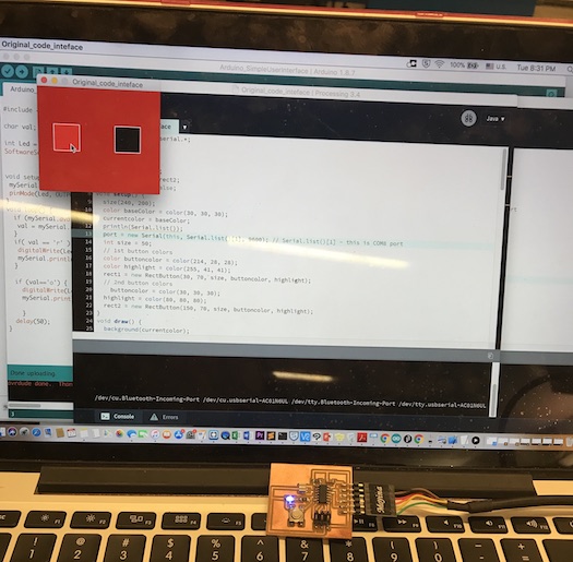
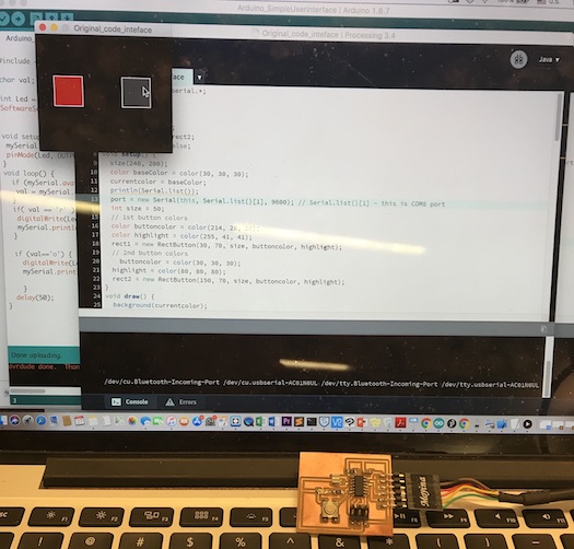
>For my Interface design, I used a platform called Processing and followed the tutorial I mentioned above.I tinkered with the code that the tutorial had to make it work with the purpose of my inteface.

The code for the Processing Platform is as follows:

import processing.serial.*; Serial port; color currentcolor; RectButton rect1, rect2; boolean locked = false; void setup() { size(240, 200); color baseColor = color(30, 30, 30); currentcolor = baseColor; println(Serial.list()); port = new Serial(this, Serial.list()[1], 9600); // Serial.list()[1] - this is COM8 port int size = 50; // 1st button colors color buttoncolor = color(214, 28, 28); color highlight = color(255, 41, 41); rect1 = new RectButton(30, 70, size, buttoncolor, highlight); // 2nd button colors buttoncolor = color(30, 30, 30); highlight = color(80, 80, 80); rect2 = new RectButton(150, 70, size, buttoncolor, highlight); } void draw() { background(currentcolor); stroke(255); update(mouseX, mouseY); rect1.display(); rect2.display(); } void update(int x, int y) { if(locked == false) { rect1.update(); rect2.update(); } else { locked = false; } //Turn LED on and off if buttons pressed where if(mousePressed) { if(rect1.pressed()) { //red ON button currentcolor = rect1.basecolor; port.write('r'); } else if(rect2.pressed()) { // all Leds OFF currentcolor = rect2.basecolor; port.write('o'); } } } class Button { int x, y; int size; color basecolor, highlightcolor; color currentcolor; boolean over = false; boolean pressed = false; void update() { if(over()) { currentcolor = highlightcolor; } else { currentcolor = basecolor; } } boolean pressed() { if(over) { locked = true; return true; } else { locked = false; return false; } } boolean over() { return true; } void display() { } } class RectButton extends Button { RectButton(int ix, int iy, int isize, color icolor, color ihighlight) { x = ix; y = iy; size = isize; basecolor = icolor; highlightcolor = ihighlight; currentcolor = basecolor; } boolean over() { if( overRect(x, y, size, size) ) { over = true; return true; } else { over = false; return false; } } void display() { stroke(255); fill(currentcolor); rect(x, y, size, size); } } boolean overRect(int x, int y, int width, int height) { if (mouseX >= x && mouseX <= x+width && mouseY >= y && mouseY <= y+height) { return true; } else { return false; } }

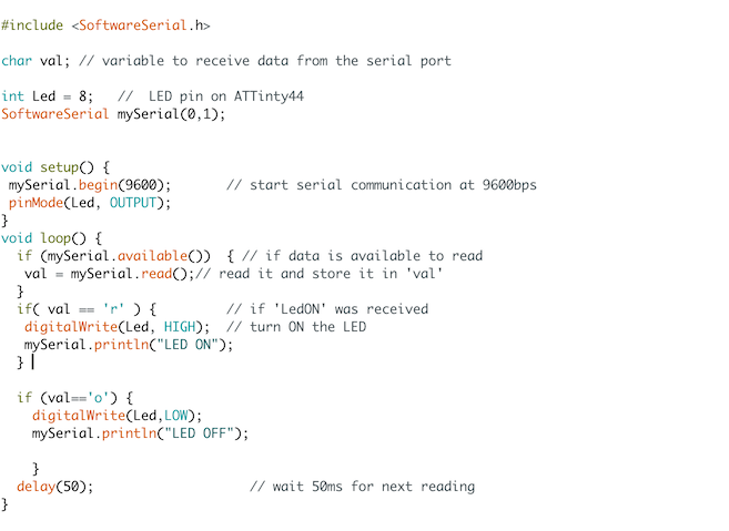
The code for the Arduino Portion of the interface was quite straightfoward. The only tricky part was establishing the serial communication between the Interface and the arduino. I ran into some problems with the clock fuses, which were then fixed by running bootloader. So, as a tip, whenever you fabricate a board, and decide to run it on Arduino, make sure you run BURN BOOTLOADER! (this will save you many hours of debugging)

Also, some notes are as follows: 1) When compliling for an attny44 board (or any AVR) using Arduino, press down shift while you press the compile button (only for the first few seconds). 2) Attiny requires you to include a special serial software library.

Arduino Code

Also, the error in the fuses prior to BURN BOOTLOADER was as follows. Notice how avrdude gives different values for the low fuse. The first one is incorrect, while the second one is.

RLE-EECS-MTL-DHCP-20-27:Java marwaalalawi$ avrdude -p t44 -c avrisp2 avrdude: AVR device initialized and ready to accept instructions Reading | ################################################## | 100% 0.00s avrdude: Device signature = 0x1e9207 avrdude: safemode: Fuses OK (H:FF, E:DF, L:5E) avrdude done. Thank you. RLE-EECS-MTL-DHCP-20-27:Java marwaalalawi$ avrdude -p t44 -c avrisp2 avrdude: AVR device initialized and ready to accept instructions Reading | ################################################## | 100% 0.00s avrdude: Device signature = 0x1e9207 avrdude: safemode: Fuses OK (H:FF, E:DF, L:FE) avrdude done. Thank you. RLE-EECS-MTL-DHCP-20-27:Java marwaalalawi$
Red Button Clicked, LED ON!

Black Button Clicked, LED OFF!

.