Output Devices

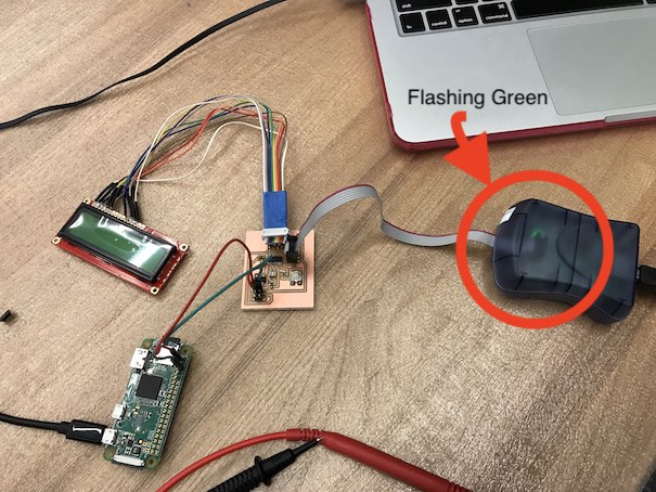
For this week, I built upon the circuit I designed last week for my final project. I used Niel's Hello World LCD board for inspiration. Because my board would be powered by a Raspberry Pi's 3.3V port, I didn't have an FTDI header, and instead had 4 pins that would provide the following to the attiny44 from the rpi: a pin for VCC (3.3 V), GND, TX, and RX. The TX and RX are both needed for serial communication with the pi. I also used a Voltage Regulator for 5V (1 Amp) given that this is the maximum voltage and current this circuit can have (from the rpi).
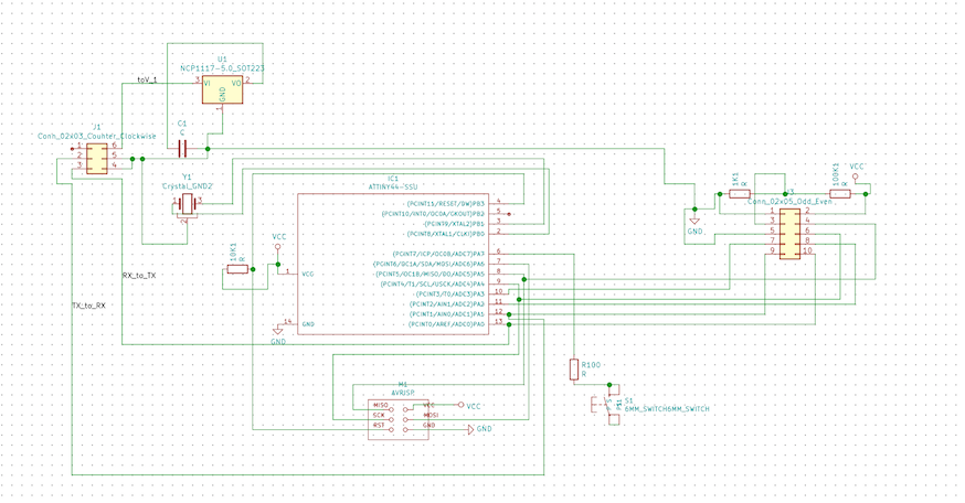
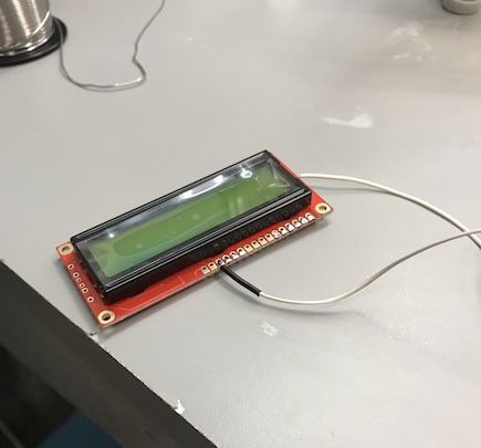
Because my final project would be utilizing an LCD, I connected the LCD to the coreesponding pins according to the data sheet and schematic above.
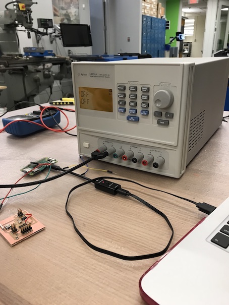
In my final project, I would be powering my board through am RPI zero's 3.3 V. Unfortunately, there were no female to female wires for me power my board from the board that I borrowed from my friends for concept checking, so I couldn't power my board.
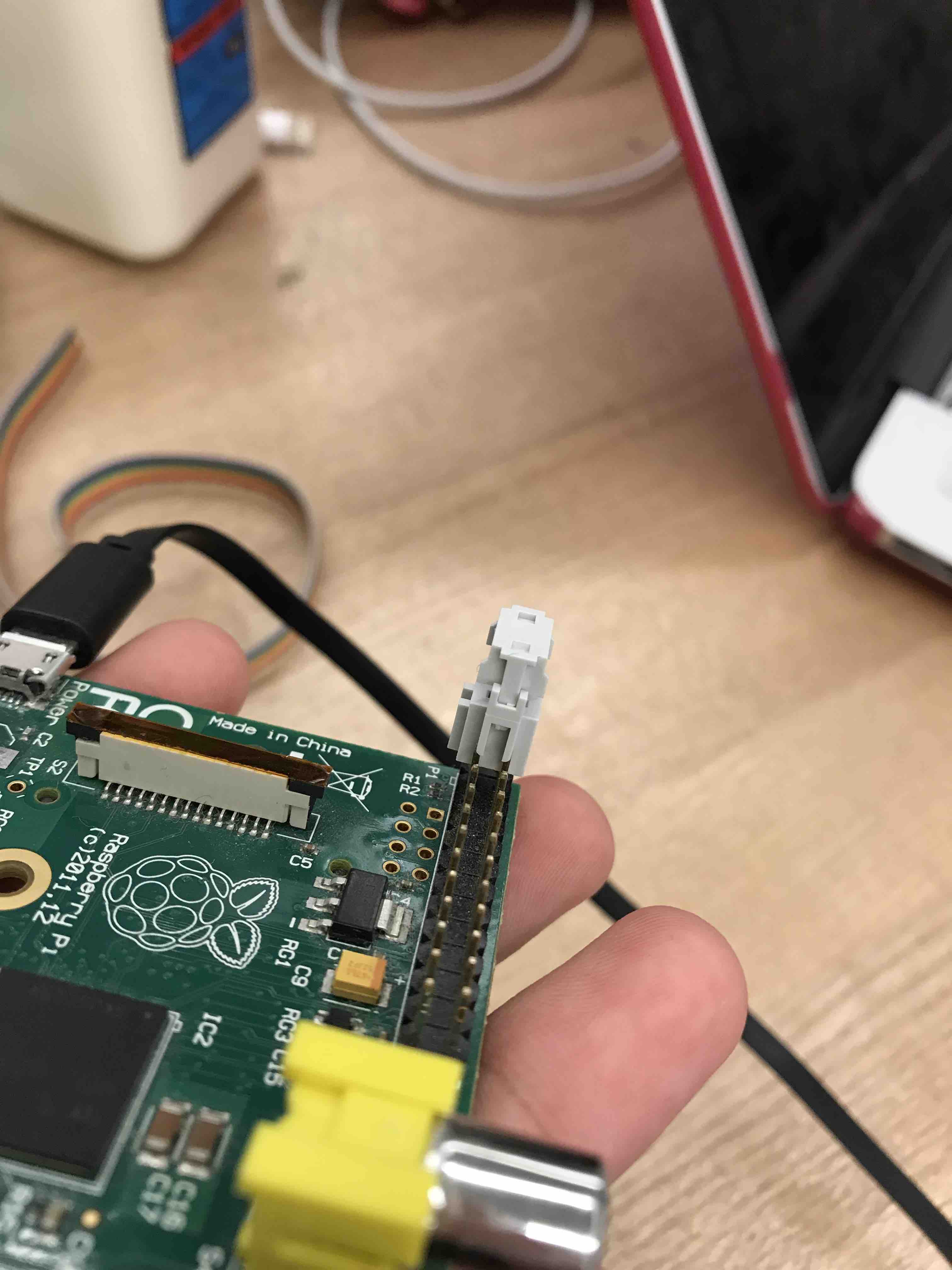
So, after getting Female to Female wires, I was able to perform the connections, but that of course came with some surprises that I'll talk about after this portion.
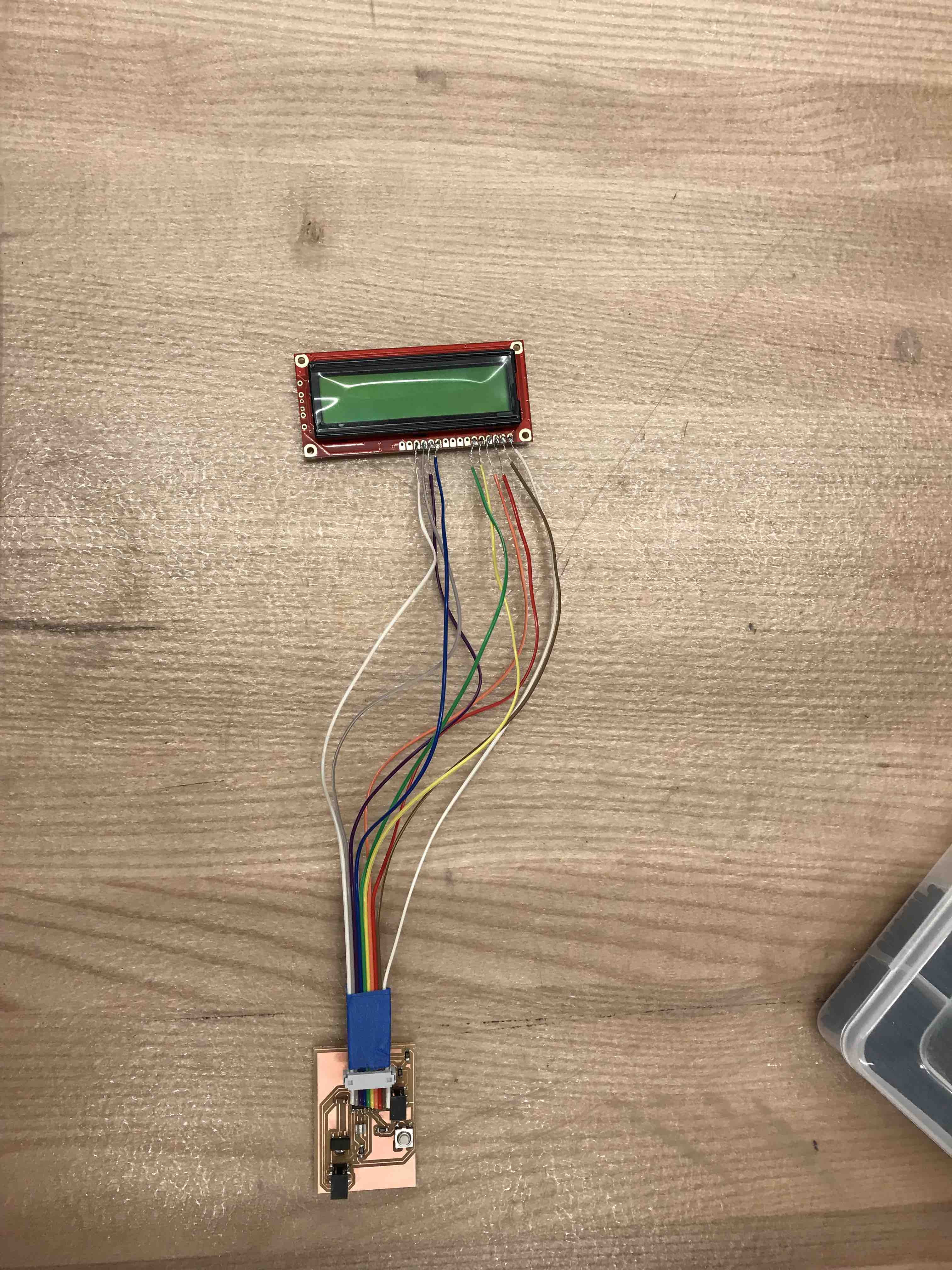
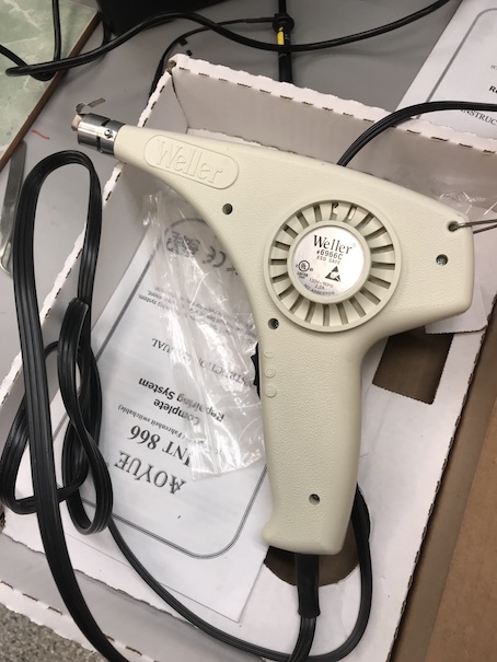
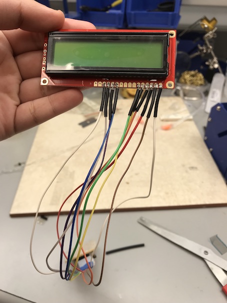
Because the wires on the LCD were prone to short out one another, I used Heat Shrink Tubes. It was my first time using them along with a heat gun. The first step was for me to desolder the wires that I had connected to the LCD, then inserting one heat shrink tube (of the diameter most fit for the wire, and of course after cutting it to an appropriate size) to the unsoldered wires. Next, I soldered the wire (I did this for each wire, one at a time) to the LCD, and lastly applied the heat gun to shrink the tube.
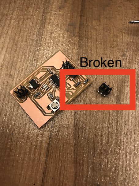
When I performed all connections, with the PI and AVR Programmer, the Board accidentally fell off the table, and the header pins connection to the programmer came off. That required milling a new board a second time.
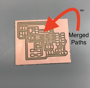
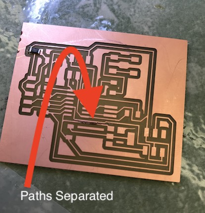
Even though I milled a new board, I was still getting errors with my circuit. A Quick test with a multimeter showed that there were paths that were joined together through milling despite being separated and following the design rules (I triple chceked with Ben). Ben speculated that this could have been an error when converting from SVG to PNG. So I used interactive routing on KiCad, which saved me a lot of time in terms of simply moving the wire paths up. Although I did that for all routes, Two routes still came merged together. So, I used an utility knife to seperate them, then double checked their separation using a multimeter.
In my original board design, I forgot to connect the VCC pin that supplies voltage from the rpi to the tiny to the tiny's vcc pin. A careless miss, I must say. Luckily I found the error myself, and fixed it using a jumper wire. Not very professional, but at least works out.
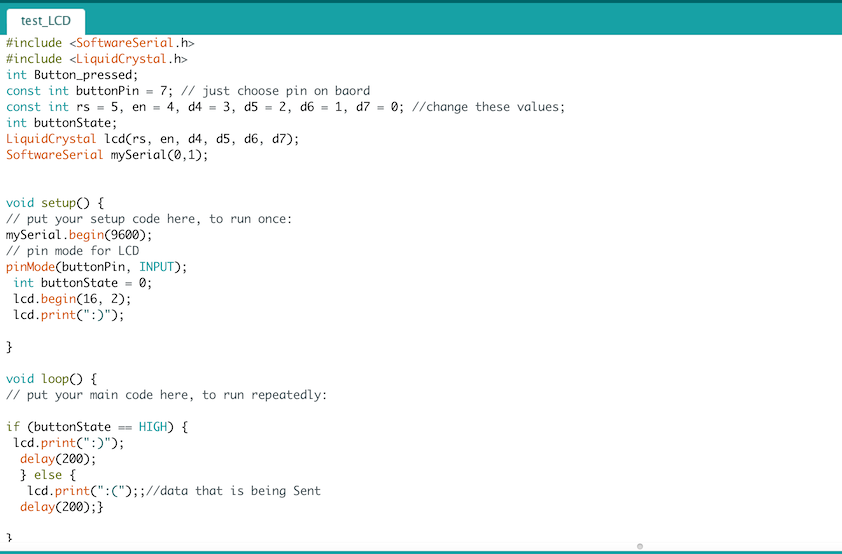
Unfortunately, the LCD is not working or doing what it is supposed to do, although the code is compiled and uploaded to the tiny. The sample code that I am using is through arduino and is as follows.
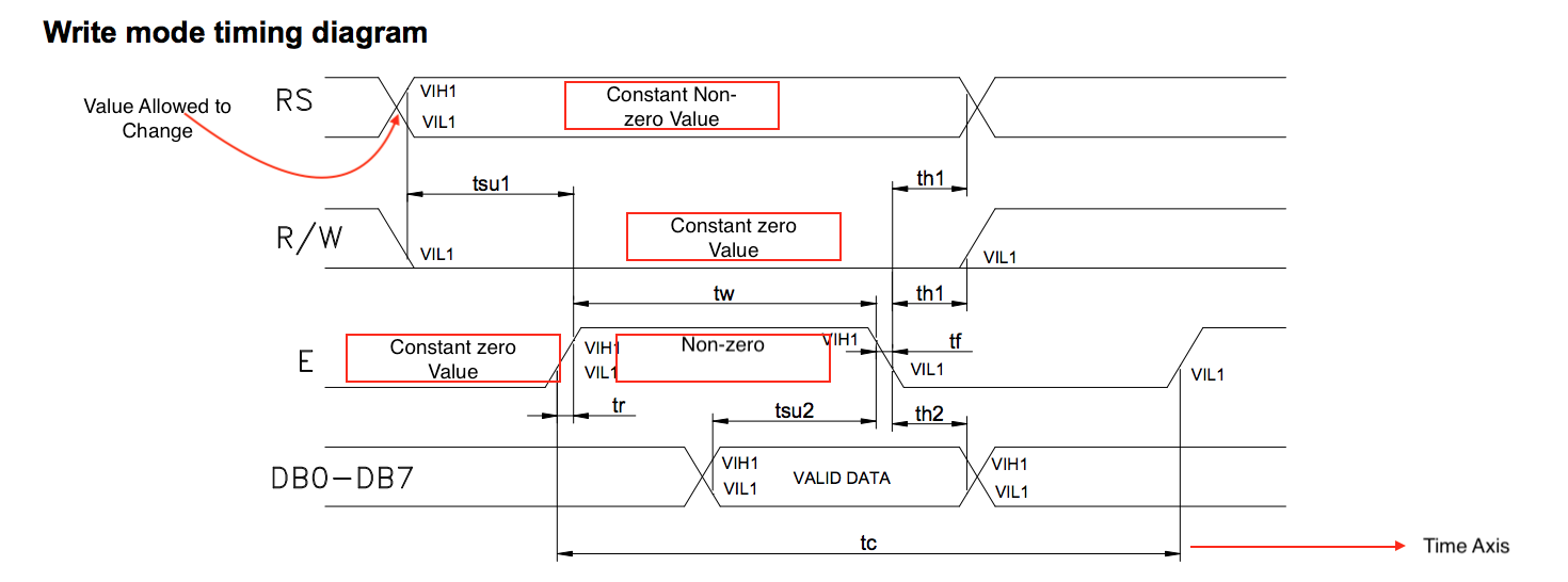
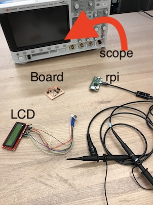
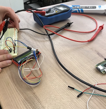
So, since the LCD s not working, the first step was to use a multimeter to make sure that all paths that are supposed to be connected to the LCD are, and that there are no shorts. Once that was confirmed, Ben suggested we move to the oscillocope to debug the issue. I looked at the mode timing diagram acording to the datasheet of the LCD module. It was my first time learning how to read cycle timing diagrams. (Requires multiple probes).
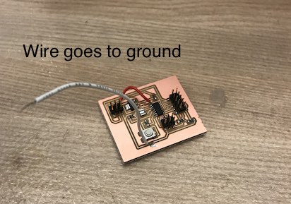
The first step was to establish a ground that the oscilloscope probes can be attached to. I simply soldered a wire to where a ground trace is on my board and attached the probes to it.
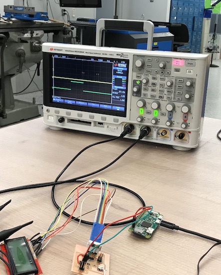
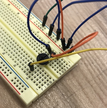
I used the oscilloscope, and although there were signals to all the pins in the LCD, they did not look like what the data sheet said. Meaning that the timing was off. Other speculations was that maybe the the contrast was set too low which is why I attached a potentiometer or varying resistor and changed its value gradually. But that also did not result in anything interesting. Of course, the change in resistor values, connection continuity, correct voltage, was all checked more than four times .
Because I have already spent more than two weeks, I decided to switch from this LCD model to a different model that instead uses an I2C communication, which should require only two pin connections (data and clock).
The continuation of Output Device Week will be documented in Networking week.
Download Traces of Serial LCD Circuit
Download Edges of Serial LCD Circuit

.