embedded microcontroller interfacing and programming,
system integration and packaging.
Prepare a summary slide and a one minute video showing its conception, construction, and operation.
Design Concept
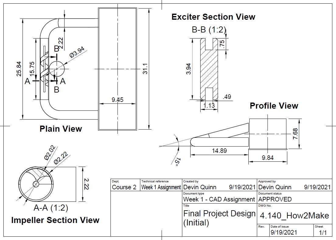
The inspiration and concept for my final project design is discussed here on my Week 1 page. In general, my goal was to create a closed loop fluid circulating system that contained no pump seals. Below is a technical line drawing created in Fusion 360 of my design concept.
Using Fusion 360 I also created an amination of the model to better demonstrate how the system will operate.
The concept of creating a sealless pumping system is nothing new. They are commonly used in the medical and chemical fields in the form of peristaltic pumps. My design more closely resembles a mixing hot plate, which excites mixing by spinning a permanent magnet. The commercial pump vendor Levitronix is a leader in developing and producing bearingless and low shear pumping systems. These leverage more advance technology, but aligns with my original aim to fabricate a pump lacking a common failure component (e.g., bearings, mechanical seal, etc.).
After progressing in the semester, I filled in some of the interconnection gaps from my original design. This hand sketch depicts my excitation mechanisms, servo motor, and tank level indicator. I am sure this design will continue to evolve as I begin the fabrication process.
Project Materials
In additional to fab lab inventory items, I gathered an array of material for my final project. The below table lists items used, how acquired, and item cost.
To ease assembly, I opted to purchase piping sections and associated fitting. I selected to purchase Powertech's dust collection piping because it was clear and the thinnest gauge wall thickest, I could locate at a reasonable price. Initially, I resisted purchasing Powertech's pipe fittings in the hope of designing and fabricating them myself, but as the semester’s end neared, I opted to purchase these as well.
This piping material is designed for vacuum applications to collect saw dust, so the connections do not couple together (the outside diameter of both items are the same). They are typically connected with ventilation tape or rubber hose clamps. For my low-pressure application, I would need to fabricate sleeves to couple the fittings and pipe sections together. I planned to accomplish this through 2D milling.
Pipe Coupling Fabrication
My initial coupling idea was to create a ring that would fit around the outside of both the fittings and the piping. Using a ShopBot in the RLE lab and its associated PartWorks3D program to generate tool paths, I milled a prototype ring out of plywood. I envisioned milling the actual rings out of Delrin to achieve a better surface for sealing, but I decided to pivot a different direction.
I liked my original design because it did not obstruct flow through the piping interior, but after realized that outer diameter of 2 in schedule 40 PVC piping was the same as my piping's inner diameter, I opted to fabricate sleeves that fit inside my piping and fittings. I viewed this as a time savings measure, because I would only need to machine one dimension of the sleeve (outer diameter to fit inside the fittings). I would accomplish this task using the lathe in the RLE machine shop.
The below images show my progression of machining. I took about 15 mils off the PVC pipe's radius to ensure my clear piping would fit over it. I had to take approximately 170 mils off the radius to ensure the fittings would fit over PVC coupling. All in all, this came together pretty well!
This is a time laspe of machining a few couplings.
Prototype Fabrication
To ensure feasibility of my design I fabricated a prototype as my week 2b laser cutting assignment. The frame includes tabs that wire can be wound around to create wire coils (indicated by the yellow dashed line). The disks that form the screw of the impeller are rotated at 20-degree increments to create the spiral. There are notches, 180-degress apart, that run down the length of the screw (indicated by the blue dashed line). This will serve as an area to affix ferrous flat stock or permanent magnets.
Over the following weeks I added permanent magnets, wire coils, and iron cores to my prototype, which allowed me to test the design during my week 7 assignment. Sadly, this was a complete failure; I was unable to induce rotation. It was time to do some electromagnet testing.
Electromagnet Testing
Using a power supply to control current flow and a Hall Effect sensor, I tested a couple electromagnets. The first was an induction coil that I added an iron core to and the second was an iron core that I wrapped 26 AWG magnetic wire around. I was not satisfied with the strength of either of these arrangements, so I decided to research what drives induced magnetic field strength.
This is the formula I found for calculating the force induced by an electromagnet on a ferrous material. In this formula, ‘N’ is number of wire of turns, ‘I’ is current, ‘A’ is wire cross sectional area, ‘g’ is the air gap distance, and ‘mu’ is a magnetic force coefficient.
After realizing that the number of turns and current run through the coil had the greatest impact on magnetic field strength, I set out on making another electromagnet with more turns and heavier gauge wire that could accommodate higher amperage.
In addition to a permanent magnet these are the electromagnets that I testing while using a power supply to provide 1 A of current. In the above image, the coil to the left was used for tests 1 and 2, the middle coil was used for test 3, and the right coil was used for test 4. The results of my testing are shown in the below table. I was content with the performance of Electromagnet 4 and planned to construct more of them.
Wire Gauge (AWG)
Coil Wraps
Core
Magnetic Field Strength (Relative Scaling)
Permanent Magnet
N/A
N/A
N/A
>500
Electromagnet 1
20
150
Air
70
Electromagnet 2
20
150
Iron
150
Electromagnet 3
26
200
Iron
130
Electromagnet 3
18
400
Iron
300
Closed Impeller Design - Casting
During week 8 I experimented with casting a closed impeller. An image of the mold is shown to the left. To follow details on this process please visit my week 8 site here. After this experience I decided that machining an open or semi-closed impeller would be more feasible.
Still being in the planning/design phase for my final project I envisioned machining a semi-closed impeller out of Delrin. Similar to a mixing hot plate, if permanent magnets were implanted in the impeller, it could be excited by a rotating permanent magnet. I experimented with creating a composite from cork and liquid plastic to serve of the stock to machine the pump's volute (pump housing). To limit the number of directions I was moving with my final project I abandoned this avenue. Below shows images of the composite pre and post clearing on a mill to create flush stock surfaces.
Screw Impeller Design - 3D Printed
I designed my screw impeller in Fusion 360 using a coil to cut away from a cylinder. Using the hole function, I added holes for permanent magnet and small penetrates through the impeller’s thickness to assist with magnet removal. My CAD file is hyperlinked to the image.
I started off by printing a same segment of the screw to verify tolerances with the permanent magnets, shaft, and pipe. Once content with this print, I moved on to printing an impeller that made 1.5 revolutions. I anticipated this being my final print, but once I set the impeller on bearings within the pipe, I quickly realized it was not balanced. I would have to print in full revolution increments to produce a balanced impeller.
Test Section
Unbalanced Impeller
Print Iterations
Bearing Retainer Iteractions
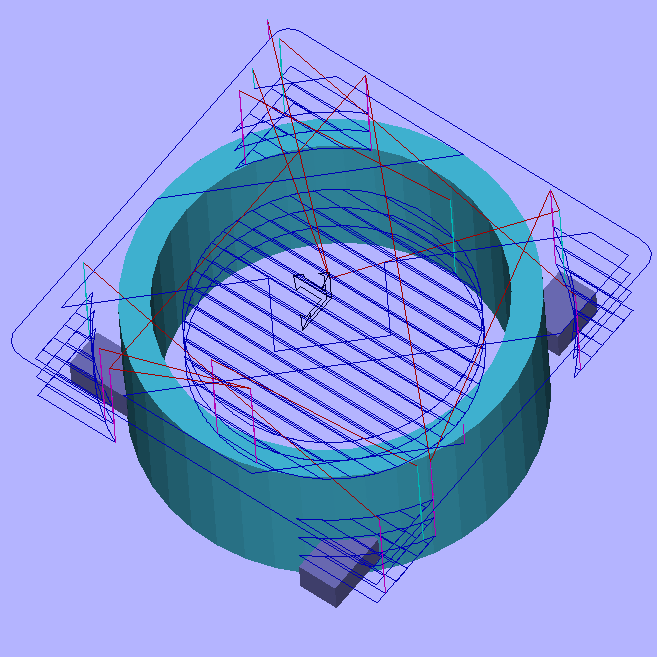
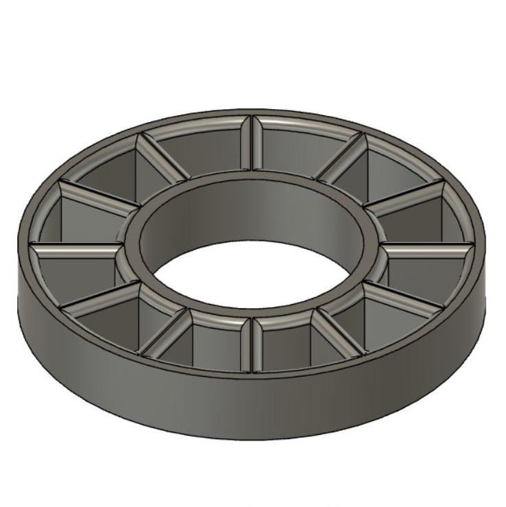
My initial bearing design (shown in the lower left image) was based on the idea of not pumped water across the bearings. This design gave no consideration to limit turbulent flow and only aimed to provide uniform support of the bearings. After running into issues obtaining pipe fittings in a timely fashion, I opted to run water across the bearings. To refine my design, I limited the number of stanchions between the inner and outer rings, created a flared profile for the stanchions, and shrouded the bearing face with a tapered cone. All of these design elements aimed to increase flow across the bearing and limit turbulence. No, I do run my model through any finite element analysis in the design process. My final CAD design is available here. My design iterations are shown in the below images.
Initial Design
Intermediate Design
Final Design
Design Iterations
This demonstrates the proof of concept for my impeller support structure and ability to excite rotation through the pipe wall. Note, this was using my initial bearing retainers.
After assembling my final bearing retainers I discovered the bearing no longer revolved smoothly. Upon closer inspection I found that the inner race of the bearing was rubbing against my retainer's inner edge. The inner race of the bearing was press fit onto the shaft, so it rotates along with the shaft. The outer race fits snuggly within the inside of the pipe and remains in place. Both the inner and outer races of the bearing have the same depth, and my closed retainer design did not account for additional space around the inner race to allow rotate. Rather than reprinting with a larger hole for the retainer, I beveled the inner edge with a round file; before and after filling is shown below.
Unbeveled Inner Edge
Beveled Inner Edge
Beveling the inner edges of my bearing retainers was effective in allowing smooth rotation.
Check Valve Development
Based on the inside diameter of my piping, I designed a check valve in Fusion 360. To ease 3D printing, I separated the check valve into three components, a valve body, plate, and flapper. My CAD file is hyperlinked here.
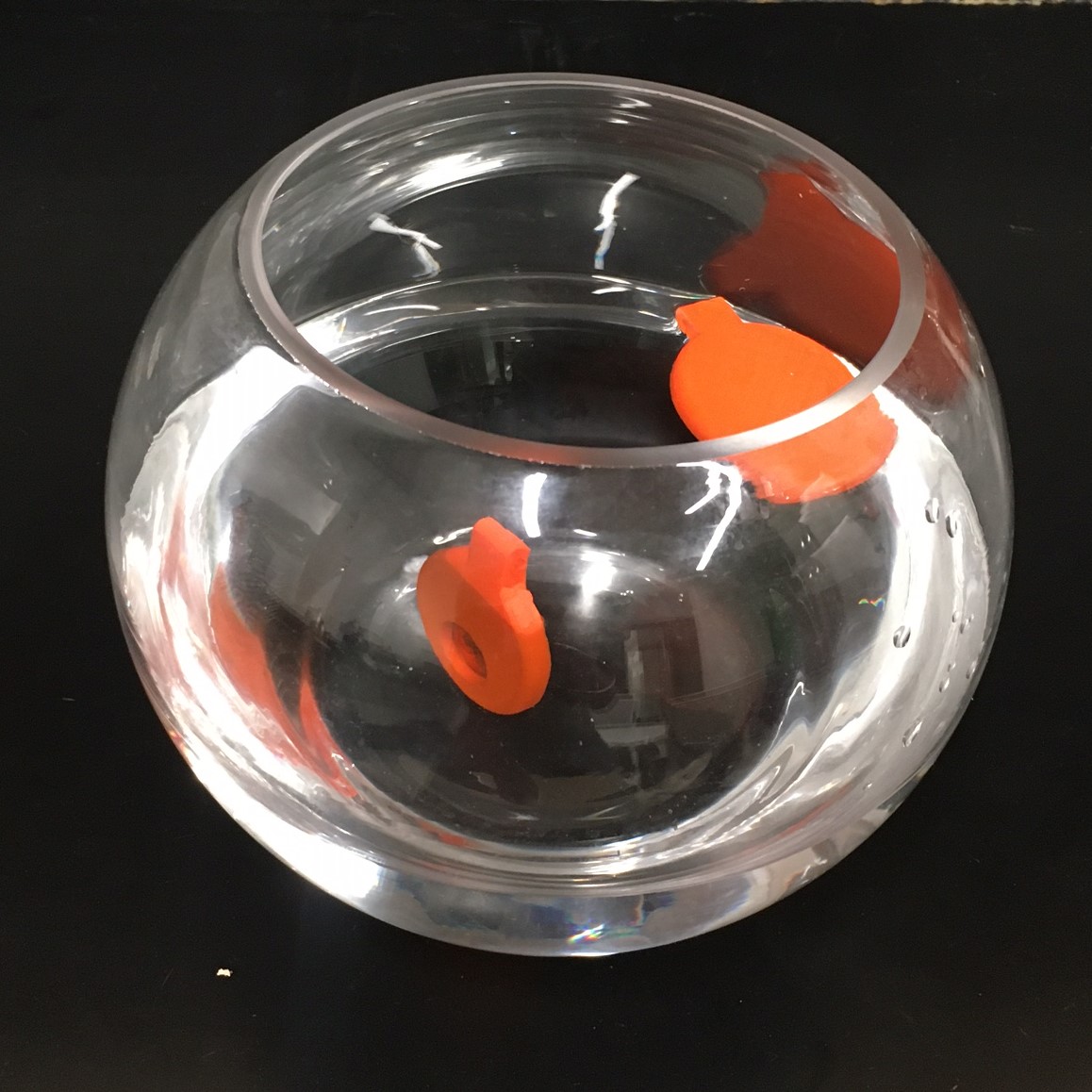
While designing the check valve flap, I realized that 3D printing with PLA may result in a component with a positive buoyancy; not what you want for a check valve flapper. After determining the density of PLA to be 1.25g/cm^3 I considered printing with 100% infill, but thought this was not a good use of materials or time. Instead, I brainstormed methods to add weight to the check valve flap. My first attempt to add weight involved pausing the mid-print to add small segments of all thread between the infill walls. After pausing the print, I failed to raise the extruder head from the component, which resulted in oozing of the surrounding area. This attempt, along with the oozing is shown below.
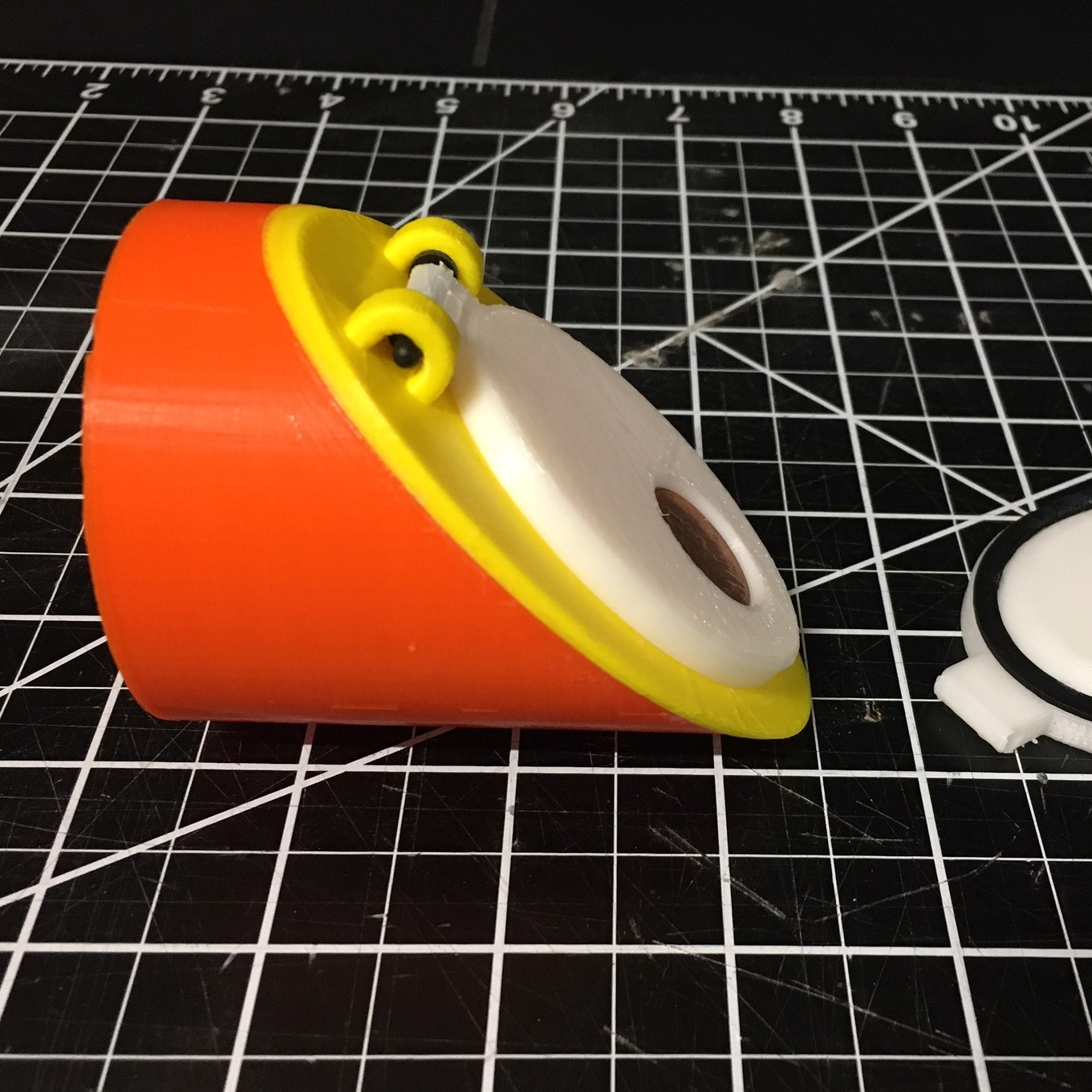
Turns out I didn't add nearly enough all thread to counteract the buoyancy of the component. My second attempt to add weight involved adding a hole to the topside of the flapper that I could insert pennies into. As shown below this was more effective.
Sadly, I encountered another issue with my check valve design; it failed to fully swing open because the shaft hole was not concentric with the hinge armature. The initial design and corrected design are shown below.
Initial Design
Corrected Design
Success! The valve now hinged open freely. I conducted a quick leak check of the valve and was content with its performance prior to adding a rubber gasket to the sealing face or grease/glue to seal between the valve body and the pipe.
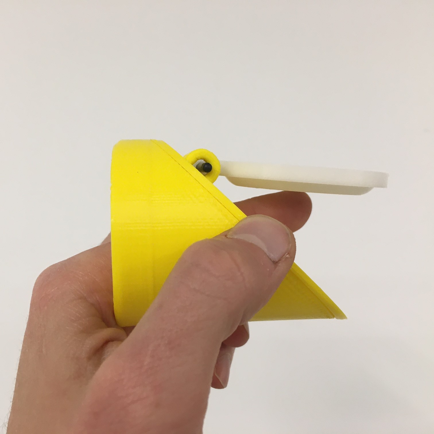
Time to move on to assembling the check valve components. Using super glue, I adhered the valve body to the valve plate. I laser cut a rubber gasket to provide a better sealing surface and adhered it to the valve flapper. In the image to the left, the valve body is orange, the valve plate is yellow, and the valve flapper is white.
Turns out the rubber gasket idea didn't work out well. The additional thickness of the gasket prevented the valve flapper from seating properly on the valve plate. I could have extended the hinge height on the valve plate to account for the additional thickness. Instead using a Q-Tip and acetone I smoothed the 3D printing lines on both the valve flapper and valve plate sealing surfaces to create a better seal.
Finished Check Valve Assembly (No Gasket)
Frame Fabrication
Similar to the frame created during week 6, I refined my design in Fusion 360 to facilitate supporting two screw impeller; one that would be excited by rotating permanent magnets driven by a DC motor, and a second that would be excited by a bank of electromagnets. The CAD file is linked to the below images. My 3/4 inch scrape plywood was not of standard dimensions, so I created a sketched of their dimensions to assist with component placement within the millable area. Per Chris Dewarts' guidance I used 1/2 inch spacing between components and milled extra components to maximize use of my plywood. I used 1 in spacing around stock edges as an added buffer.
With less assistance than required during week 6 I finalized my CAD design in Rhino and developed the G-code for milling in MasterCAM. In Rhino I created a design layer of points at all internal notch corners to create dog boned connections and another layer of the component outlines using the silhouette function. Initially, I was modifying a .STL file in Rhino, but was unable to remove the surface triangles lines of the .STL file, so I re-exported my design from Fusion 360 as a .DXF and experienced success with creating the two layers.
After hand tooling several components, I started to fit them together and noticed a flaw in my design. With the frame I created during week 6 I filleted the outside corners of each notch to assist with alignment while fitting together. I failed to carry over this feature to this frame and as shown to the left it was rather difficult to assemble some components. To alleviate this, I spend a little more time hand tooling with a file to round the notch corners. The below images depict the design feature I failed to carry over to this frame.
Filleted Notch
Non-Filleted Notch
After a substantial amount of hand tooling, I finally had a frame that fit together. Hurray!
Exciter Disk Fabrication
I did a little math prior to fabricating my exciter disk. The below image shows my calculations for determining disk diameter. In general, I aimed to match the lateral magnet spacing of my screw impeller and exciter disk. I selected to use eight magnets to increase the rotational speed of my impeller.
I created my exciter disk design in Fusion 360. The CAD file is available here. Prior to laser cutting the disk, I did a test print of the hole cut out for the motor shaft. I was extremely pleased with the press fit tolerance of the motor shaft, so I proceeded to cut three disks using 1/4 inch acrylic. After laser cutting, I sandwiched the three disks together with super glue to create a disk of adequate thickness for embedding 1/2 inch diameter permanent magnets. Next, I used the Acer mill in the RLE machine shop to create 1/2 inch by 1/2 inch holes for embedding the magnets.
PCB Fabrication
I fabricated the boards shown to the left as part of my week 11 assignment. The long skinny board contains a Hall Effect sensor that will act as a high-level tank indicator. The other board will drive a servo motor to open a drain valve based on the input from the Hall Effect sensor. Visit my week 11 page for details on the fabrication of these boards.
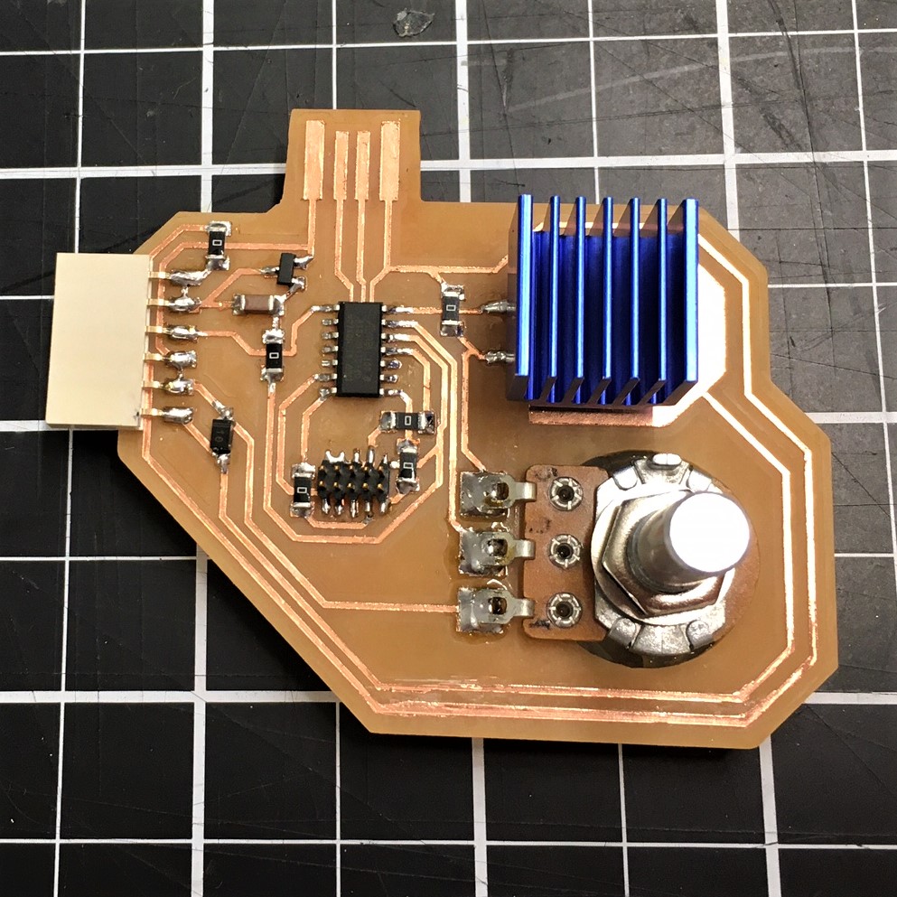
I fabricated this board as part of my week 12 assignment. This will act as my main PCB that will control pump speed and also receive an input from the Hall Effect sensor. Visit my week 12 page for details on the fabrication this board.
While wiring my boards together I realized I would need to split the Hall Effect sensor signal to two boards. Rather than splitting and splicing a wire, I decided to mill a junction connector that could be used to split the sensor input and maintain a consistent ground and VCC across the three boards. As shown in this schematic it is simply two 6 by 1 connectors butted together. The CAD file for this design and available here.
I envisioned fabricating PCB cases that consisted of two plates sandwiched together with spacers in between. I planned to use clear acrylic for the top plate, so the circuitry would be visible. To accomplish this, I started by importing my board outline .PNG files into Fusion 360. Using the calibration command, I ensured the imported images were properly scaled for the actual boards. The CAD file containing my laser cut items is available here.
Assembled Cases
Board Coding
The codes for my motor and breakout boards are fairly simple. The motor board receives inputs from the potentiometer and Hall Effect sensor to control motor speed. The breakout board microcontroller receives an input from the Hall Effect sensor that activates a servo motor to open a drain valve. The codes are hyperlinked to their respective images.
Motor Board
Breakout Board
Interconnections
This is my arrangement for testing operation of my interconnects prior to final wiring. Everything was working properly, so I moved on to heat shrinking connections. After heat shrinking, I realized I would have to cut away a couple of the heat shrink wraps to allow for final assembly, but left everything as is to prevent crossing any wires.
Testing - Round 1
I used hot glue to assembly my piping but left the pipe section containing the impeller unglued to allow for disassembly. Knowing these connections would not be watertight, I used my sandbox bin as a containment pool.
This testing was a pretty big disappointment. I was only able to achieve about a 1 inch difference in head pressure between my inlet and discharge pipe sections. I would need to increase torque of my impeller to increase head pressure, so I searched for alternate DC motors.
These are the DC motors I acquired for testing. The two on the left were used in the testing shown above. I planned to use the right two for future testing. The left motor was rated to be operated with 5 V. Both of the center motors were rated to be operated with 12 V. The one on the far right is from a 24 V battery powered weed wacker. All four motors have gear reducers.
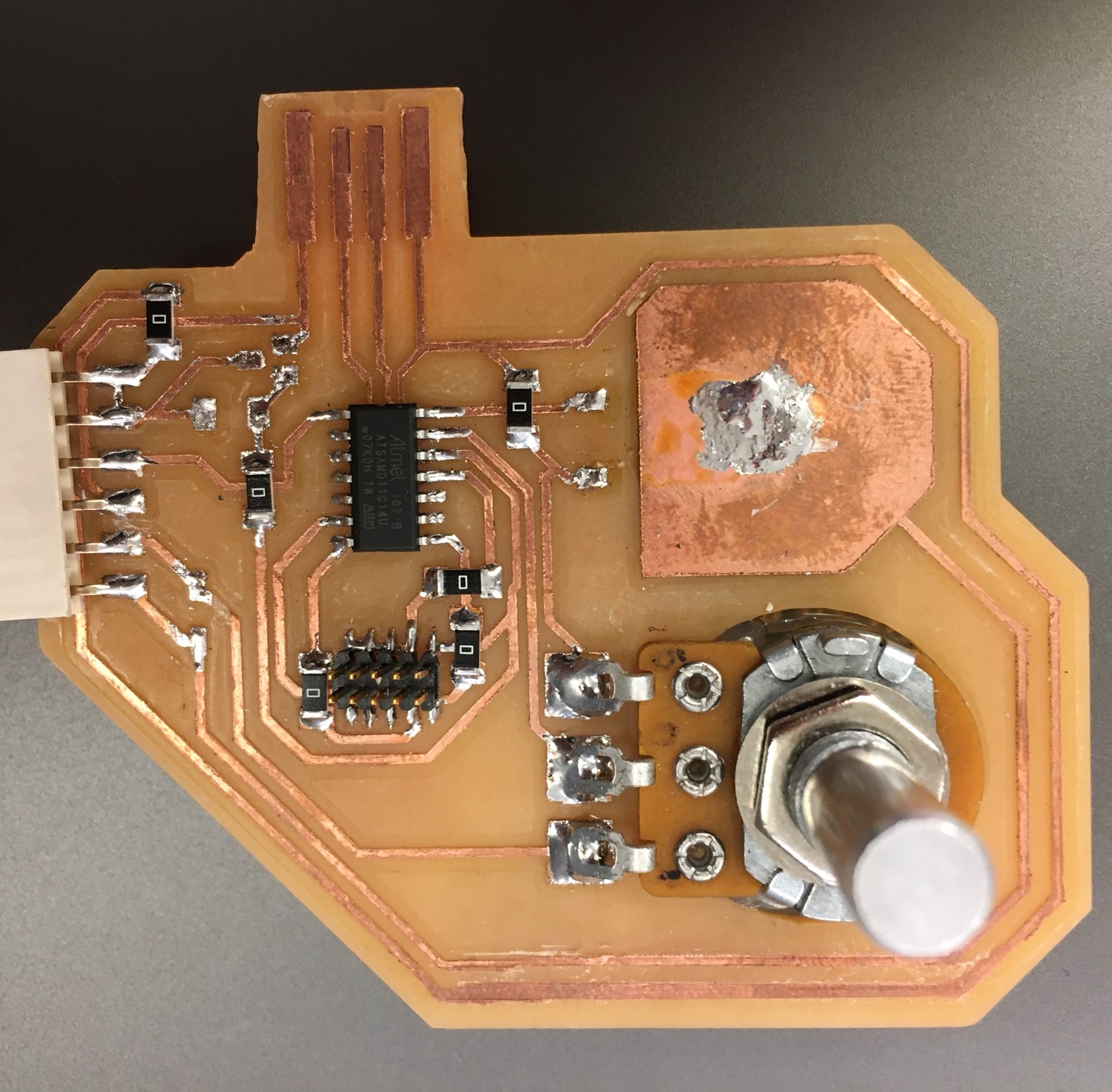
I had used my motherboard without issues for the past couple of weeks, but suddenly started experiencing issues with the microcontroller. These issued stemmed from two sources. Initially, I was using the board to power a 5 V motor, but transitioned to using a 12 V motor that I powered externally via a power supply. My diode protection circuit was no longer dumping back to the motor's source voltage (12 V), but instead it returned to the board's source voltage (5 V). Additionally, I was powering the potentiometer with 5 V, which returned 5 V to the microcontroller at its highest setting. Both of discrepancies resulted in burning up a few microcontrollers, but after performing a little board by routing the diode protection to a jumper connection and manipulating the VCC trace for the potentiometer, I no longer experienced issues.
Gutted Board
Fixed Board
Keeping ferrous metals submerged in water is never a good idea, but I did not expect my bearing to begin deteriorating within 24 hours. At this point I considered turning my contraption into an auger to move plastic beads. I experimenting with this and quickly realized my design would require significant modifications to make this work, so I swapped out to a new pair of bearings that I coated with oil prior to installing.
Testing - Round 2
Prior to proceeding to my second round of testing I had to modify my motor bracket. I accomplished this by using a hole saw.
Dry Test
Wet Test
Everything ran well during the dry run, so I decided to give the wet test another run. With the new 12 V motor I was able to achieve a rise of 1.5 inches on the discharge side. Combined with a drop of 1.5 inches on the suction side, this test run achieved a total head difference of 3 inches while running at 12 V and 2 A.
Running the motor beyond 14 V resulted in the exciter disk over torquing and jump magnetics on the impeller. To increase torque between my exciter disk and impeller I narrowed the gap between the two by deepening frame notches with a file.
Flange Fabrication
I had to fabricate a flange to connect my piping to the inlet reservoir. I designed a five-bolt flange in Fusion 360. Milling was my first choice for fabricating the flange, but with time winding down I pursued multiple tracks for creating a flange.
First I started a flange print on a 3D printer, and then I generated toolpaths for milling on a ShopBot the RLE lab. I encountered a couple issues with the ShopBot mill and had to stop the milling prior to finishing; fasteners holding the z-axis power screw loosened and the dust collection system started to leak. All in all, I will end up using the 3D printed flange.
The final product for my supply reservoir is shown to the left. I also printed a flange to fit the drain valve in my discharge tank; it is shown to the right.
Final Assembly
I started by assembling my tanks and the actuator assembly for my drain valve. I used fishing line for my magnetic float to ride up and down. The fishing line worked, but it was a little stiff to allow for free motion, so I may swap to thread for the final presentation.
Next I assembled the frame for my tanks. I added bolts to each corner of the frame to allow me to adjust the height to fit the piping system. I drilled under sized holes, so the bolts would thread into the wood.
After full assembly it was time to conduct my final round of wet testing.
Testing - Round 3
At best I was content with final testing. Sadly, my drain valve did not seal as well as I would have hoped, so I swapped it out for a toilet drain valve. It was a knock on my pride to swap from a self-made component, to a pre-fabricated item.
Project Evaluation
Overall, my sealless impeller does not perform as well as I would have hoped. By only achieving a head pressure of 3 inches I was not able to stack the tanks on top of each other. Instead, I had to stack the tanks side by side. I did not expect my drain valve to seal perfectly, but was disappointed that I had to replace it with a manufactured valve. I also ran out of time on fabricating an electromagnet excitation mechanism, which is why my frame is sparse on one side. However, I can confidently say I learned a tremendous amount throughout this course, more than in any single course I had taken prior. Thank you!
