The group assignment this week entailed comparing the performance and development workflows of various microcontrollers. However, prior to diving into this assignment, I wanted to better understand the difference between digital and analog pins on the microcontroller. Both pin types can act as inputs or outputs for the microcontroller, but their capabilities differ greatly. A digital pin only has two positions (e.g., ON or OFF, HIGH or LOW, 0 or 1, etc.). Controlling the ON/OFF of an LED can effectively be done with a digital pin. An analog pin can have an array of positions with fine or coarse increments that can be scaled to the desire of the user. For example, an analog pin can be used to control motor speed. It is my understanding that through code, one can adjust the duty cycle of a digital output (e.g., square wave ON period duration) to simulate an analog signal. I look forward to experimenting with this in the coming weeks.
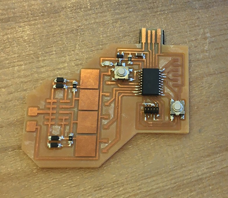
Everyone in the EECS section used either the SAM D11C or the SAM D11D this week. Beyond the obvious differences of pin count and package size, there are more similarities than difference between the SAM D11C, D11D (20 pin), and D11D (24 pin). The below table outlines some of the similarities and differences.

My primary takeaway from this comparison is that increasing to a larger SAM D11 microcontroller offers more converters and interfaces, but you are still operating with the same programming architecture and kilobytes of memory. The ARM Cortex-M0+ core has two 32-bit bus interfaces. One is an AMBA-3 AHB-Lite interface that connects to peripherals and system memory. The other is an Input/Output port interface.