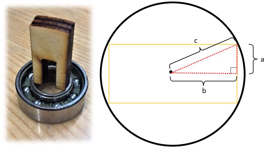
#1: My initial design contained a major flaw, the designed width of the shaft components was set to the inner diameter of the roller bearings minus the anticipated kerf. This failed to account for the inner race's curvature and the material's thickness. As shown below I needed to apply a little trigonometry to determine the correct parametric formula for the shaft component width.
- "a" is half the material thickness
- "b" is half the distance of the shaft width
- "c" is the inner diameter of the bearing
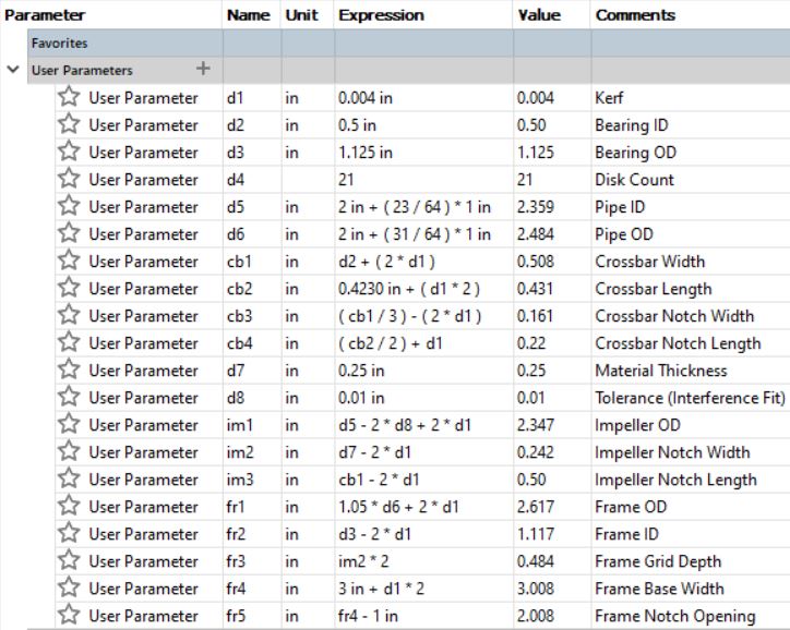
After refining the parametric width formula to, 2*(sqrt((c^2)-(a^2))+2*kerf), I had success creating an interference fit shaft for the roller bearings.
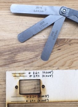
#2: There where several small sheets of 1/4in plywood that I used to create my model. After changing to a different sheet, I noticed the power necessary to cut through the sheet varied. I suspect this is because the plywood sheets I used had been sitting on the cement floor of my garage for quite some time and likely contained different levels of moisture depending on where it was in the stack. Using a different power effected the kerf of the laser and ultimately the fit of several components. To avoid this in the future I will ensure homogeneity of my material prior to using it for laser cutting.
