The group assignment this week involved reviewing the safety data sheets (SDS) for each of the molding and casting materials being used, as well making and comparing test casts. In general, the SDS information for the products being used were very similar. They all recommended avoiding eye and skin contact by wearing vinyl gloves, long sleeves, and safety glasses, as well as working in a well-ventilated area. The SDS also contained information pertaining to the safe storage, disposal, first aid, and hazards associated with each product. I will point out additional pertinent SDS information for each product below.
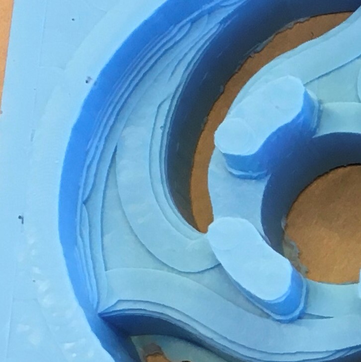
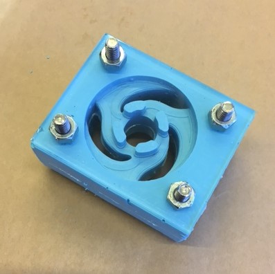
It is nearly impossible to remove a rigid casting material from a rigid mold. The machinable wax is inherently rigid so it can to machined, so if you are using a rigid casting material an intermediate step must be taken to create a flexible mold. Note, if you are NOT using this step your CAD model must be a negative of the part you desire to make, because it will be cast directly from the machinable wax mold.
This can be done by using Smooth-On's Oomoo 25, a 2-part tin cure silicone rubber that has a 15 min pot life, 75 min cure time, and is a 1:1 mix by volume. This product has a limited shelf life and should be used as soon as possible after opening (~1 week).
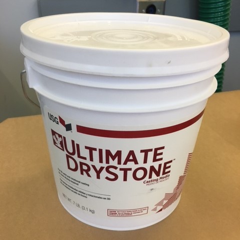
Both DryStone and HydroStone come in a powdered form and are mixed with water to create a semi-thick slurry. The mix ratio is 100:22 (powder:water) by weight. Minor deviations from this ratio will not effect casting quality, but will effect cure time (e.g., thicker mix = faster cure).
DryStone and HydroStone casts can be demolded after 30 minutes. Similar to concrete, both continue to harden for days and are excellent in compression, but terrible in tension (HydroStone actually contains cement). As with most fine powders, care should be taken to not inhale airborne particles; glad we are all still wearing masks.
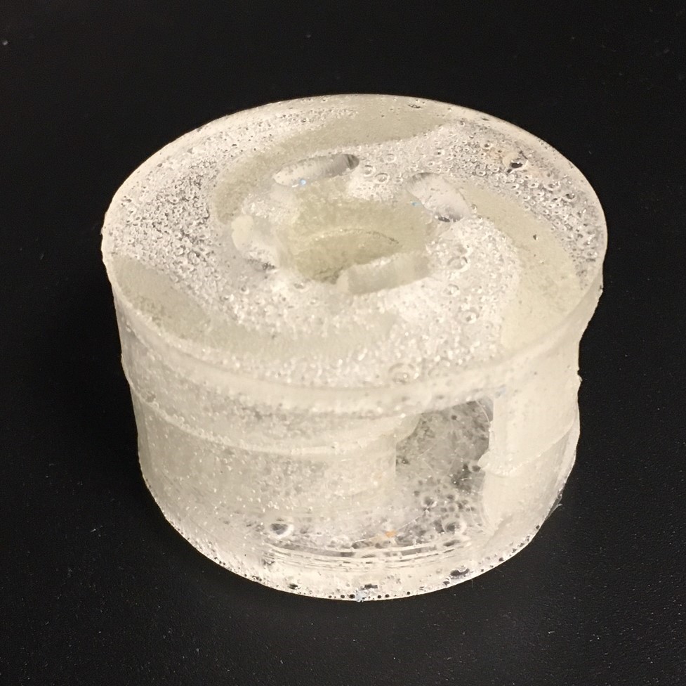
Using Liquid Plastic as a casting material requires additional safety measures due to the off gassing that occurs while the material is curing. These gases present a respiratory hazard that requires additional exhaust ventilation. This was accomplished by affixing an exhaust trunk near the cast throughout the curing process. This casting material has a 9 min pot life, 60 min cure time, and is a 1:1 mix by volume.

During weekly training, Anthony demonstrated the use of dyes to add color to casting material. During recitation he also presented castings of the same part using a variety of finishing tool paths (e.g., contour, parallel, and scallop) to mill the wax mold. There were slight differences in the finished appearance of each casting, but no decipherable difference in overall surface finish quality. It seems that a combination of the finishing tool paths will result in the best final product, as each tool path has different strengths and weakness, which are described well in the manufacturing tab of Fusion 360.