Week 13: Application Programming
This week's assignment was to "write an application that interfaces with an input &/or output device."
I ended up spending very little time on this weekly assignment but countless hours on my final project.
- Python + Matplotlib + Serial port
- DishPenser Servo motor controller
- DishPenser Dual DC motor controller
- DishPenser User Interface
- DishPenser Fabrication
- DishPenser CAD update
Python + Matplotlib + Serial port
Last week I presented my strain gauge amplifier. All the plots were made with Matlab. This week I obtained the same results but in Python.
I started by playing with Neil's term.py program. The first challenge was to get VMWare to grab my serial peripheral. I couldn't connect any external
peripheral to the VM, it seems that Windows wasn't releasing them. I ended up upgrading to the latest version (10) and it fixed that bug.
At this point I could receive bytes from my board. Recombining two bytes in one uint16 number should have been simple… but it took me a lot of trial and
error. I'm still very new to Python and I just couldn't figure out how to transform a string in raw values. I finally found a post on Stack Overflow that
explained how to do that with struct.unpack.
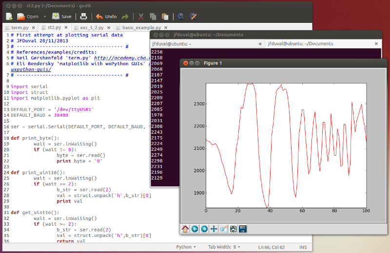
Now that I had my data in Python, I started playing with matplotlib. I found some examples online that I modified to make it "realtime". The results are
visible on the following screenshot. The code is here.
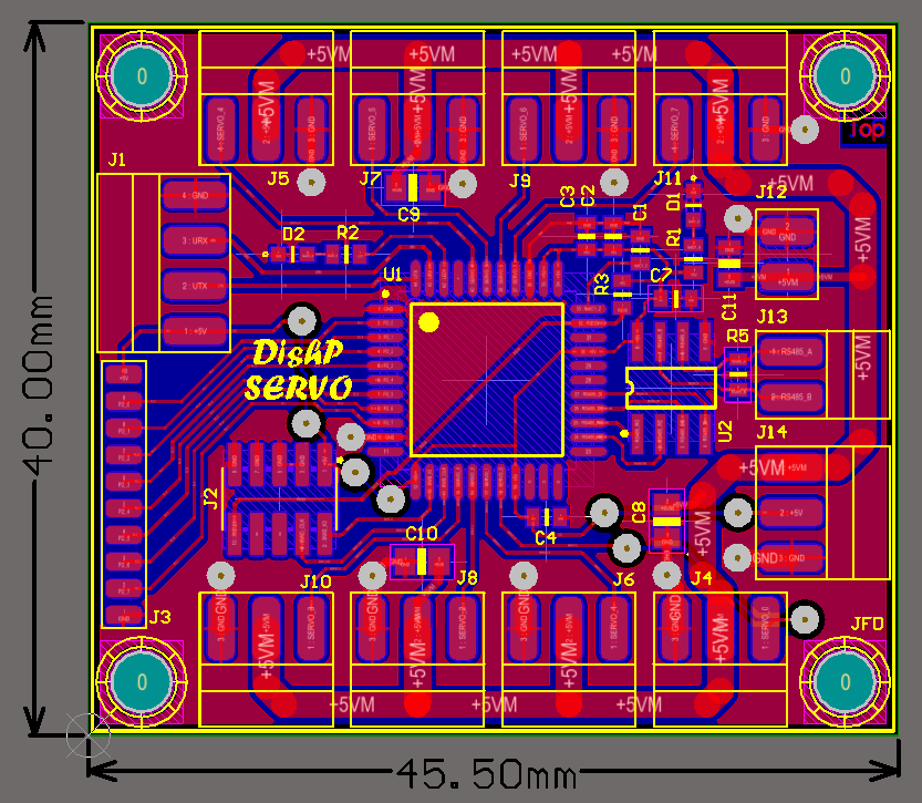
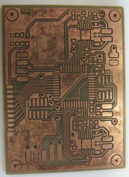
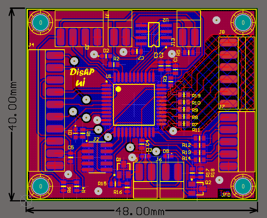
Servo motor controller
For the DishPenser I'll need at least 3 servo motors. I designed a board that can support 8, just to be safe. It is RS-485 enabled, can drive 8 motors and has 8 GPIOs on a breakout connector.
In a previous Digikey order I ordered some CY8C4125AXI-483-ND chips along with the CY8C4245AXI-483-ND I use everywhere. They were cheaper, and at first glance I thought they
were almost the same (but 24MHz instead of 48MHz). They are not: the 4125 has no Universal Digital Blocks (UDBs). I only realized that after it was soldered, when I got an
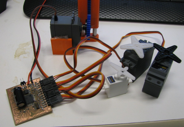
error while programming a clever servo driver using the hardware PWM module and a digital de-multiplexer to time share the servos. I ended up using fixed-functions PWM instead.
Not as elegant and efficient, but it works for now (with 4 servos). I can always write timer code, or swap the chip later if I need more than 4.
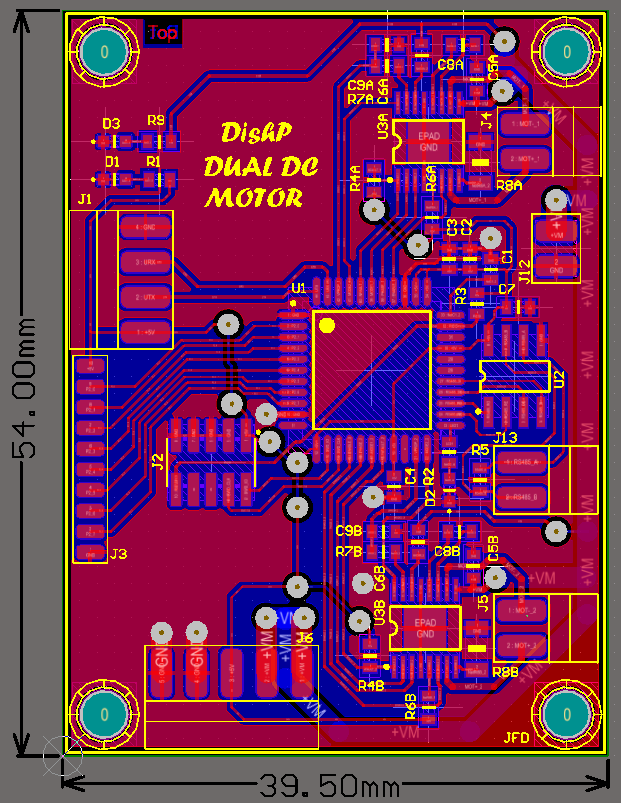
Dual DC motor controller
While ordering TI samples a couple weeks ago I found the DRV8801 motor driver IC and I added 2 to my order. It's spec'd for 40V 2.8A, similar to the A4953 (40V 2A). From those specs
only, there wasn't any good reason to use that part instead of the A4953. But, from using the A4953 in the past
(for that project: VUE32) I knew that I couldn't go nowhere near the 2A spec without a well-made and
engineered PCB and/or a heatsink (and maybe some liquid nitrogen too). The motor I'm planning to use has a stall current of 1.3A: I want the bridge to
be able to sustain that without any issue.
I started comparing the datasheets for numbers that are more linked to physics than marketing.
DRV8801: Theta-JA = 43.9C/W (TSSOP16 with pad), RDSon = 0.85 ohm (max, 125C)
A4953: Theta-JA = 62C/W (SOIC8), RDSon = 1.6 ohm (max, 125C)
Worst case scenario: ambient temperature of 35C and a current of 1.5A.
DRV8801 : P = I² * (2*RDSon) = 3.825W. T = 202C
A4953: P = I² * (2*RDSon) = 7.2W. T = 481C
Let's make that clear: both chips will die in that scenario. They can't sustain 1.5A continuous. But the DRV8801 is much closer to the maximum junction temperature of 190C, so I'll
use this one. And I'll make sure never to stall my motor (it's never a good idea anyway).
I have yet to assemble and test this one.
DishPenser User Interface
The goal: having a better user interface than the 3rd floor coffee makers (ok, I'm setting the bar real low here…).
I need 4 buttons: Load, Unload, Clean One, Clean All. I decided to use a small LCD to display the actual state.
This board is RS-485 enabled, supports a HD44780 compatible LCD, up to 5 CapSense buttons and 4 15mA LEDs (button light ring).
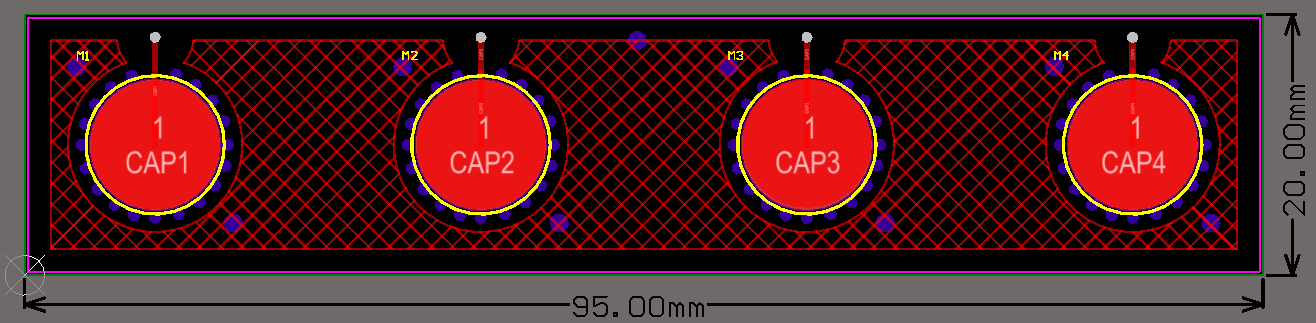
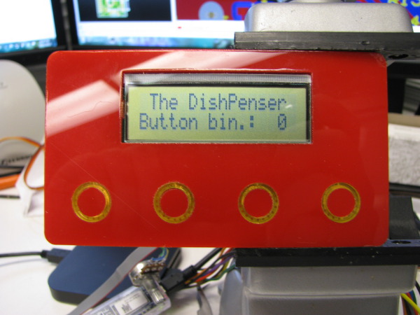
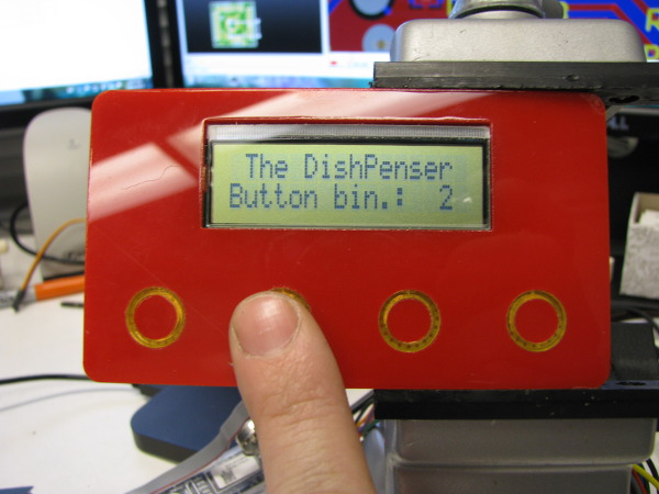
I'll add a black sticker to hide the LCD paper connector and add labels to the button at some point. I also need to realign the capacitive switches as they are not perfectly
aligned to the acrylic buttons.
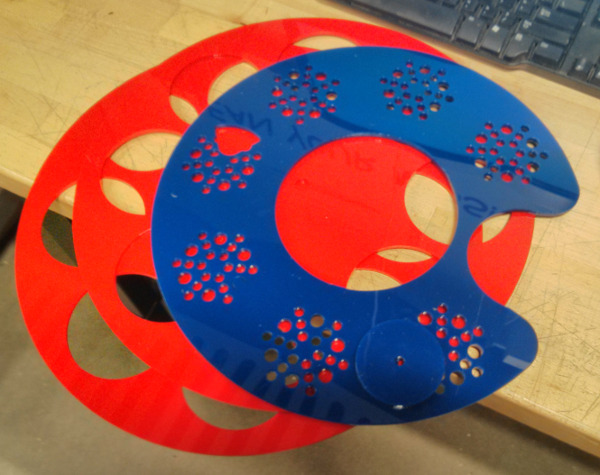
DishPenser Fabrication
The red acrylic front panel of the user interface is only a small fraction of what I've made in the Thanksgiving holiday.
Here's the result of my first session with the laser cutter:
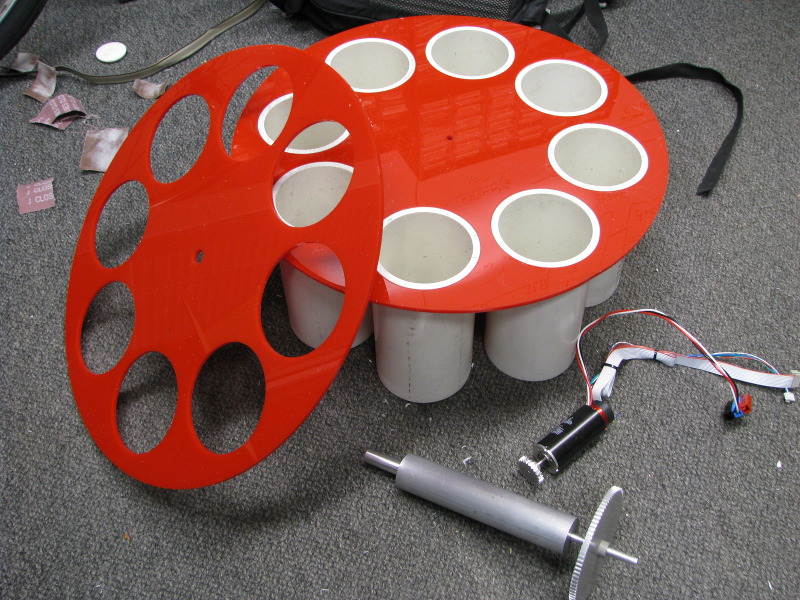
I used the horizontal band saw to cut my PVC pipe in 8 160mm pieces. I was able to get less than a millimeter of length variation, not bad for that tool! After
some sanding I was able to insert the tubes in the red plate. John trained me on the shop's big lathe and I made the main shaft.
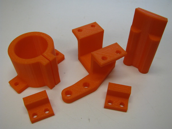
3D printed parts (MakerBot Replicator 2):
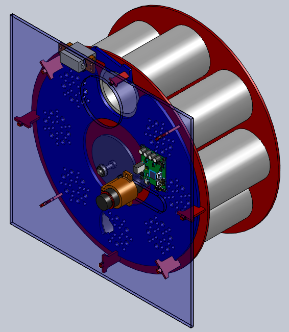
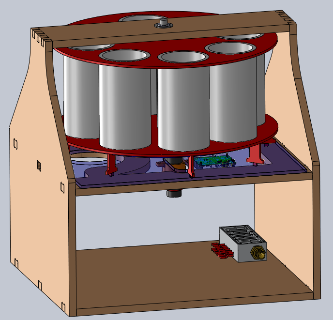
DishPenser CAD update
Although I made a lot of pieces, I can't test the design yet as some parts are missing. I updated my CAD with the measurements taken on the fabricated pieces. I
designed many new parts (Maxon mounting clamp, glass blocking mechanism, bottom plate, etc).


Jean-Francois (Jeff) Duval - jfduval(@)media(.)mit(.)edu - 2013
Top | MIT Media Lab | How To Make (almost) Anything 2013 | Index
"Hidden" keywords: Jean-François Duval, JFDuval, Jeff Duval, PCB, Dishpenser, MIT Media Lab, Biomechatronics, Electronics, Robotics, DIY, Hack, Hacker