Week 8: Embedded Programming
This week's assignment was to "program your board (the one designed in the Electronics Design week) to do something, with as many different programming
languages and programming environments as possible".
This week I:
- Designed a high-power LED board
- Fabricated my first double sided PCB on the Modela
- Assembled, programmed and tested the first prototype of that LED lamp
- Water jet cut an aluminum heatsink
- Programmed some of the functionalities of the BLDC driver I designed in Week 6
- Did research and design for my final project
High-power LED PCB design
This section is about the LED board for the Fifty SHades of White project. Refer to Week 7 for more details.
The shape of the PCB was determined in Solidworks while I was designing the molded case. I exported the PCB as a STEP A214 file. I then imported it in
Altium and defined my board outline from it. (For all the details, refer to those two
videos: Interfacing to Altium Designer from SolidWorks - Part 1 & Interfacing to Altium Designer from SolidWorks - Part 2)
My initial plan to keep everything as simple as possible was to design multiple one layer PCBs. I sketched a rough layout that allowed me to route 4 strings of 4 LED in a single layer:
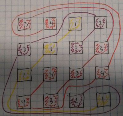
I wanted the placement to be as random as possible to get a good mix of colors. Satisfied with this placement, I started drawing the schematic in Altium.
If it was only for the LEDs, a single sided board would do it. The thing is that I need series resistors and low-side switches too. I can't place them on
the same side as the LEDs: they would interfere with the aluminum heatsink.
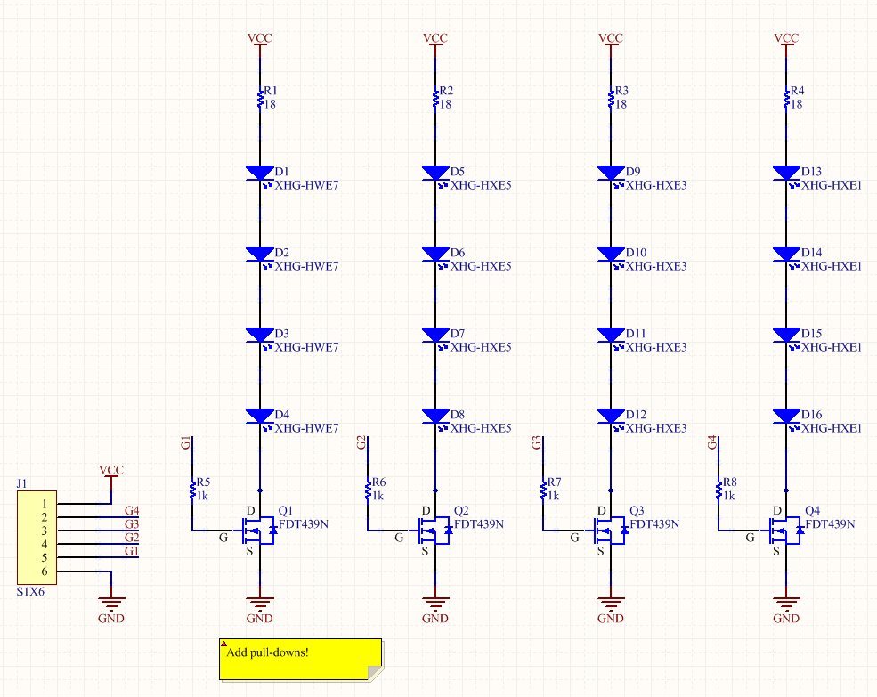
At this point I decided to go for a 2-layer board. Here's the schematic:
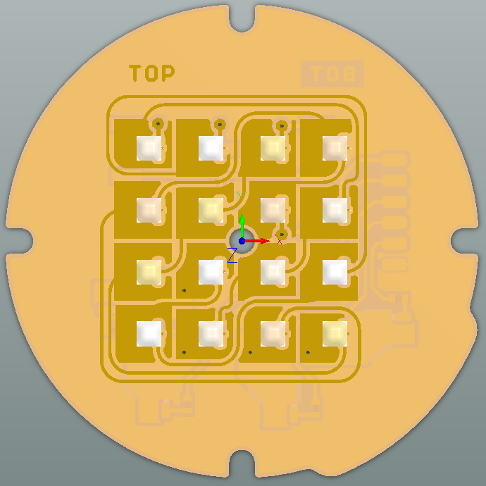
And here's the PCB:
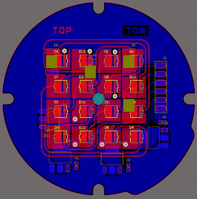
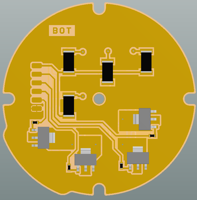
To reduce the chance of misalignment problems I used slack specs while designing: minimum 15 mils traces and 17 mils spacing, big vias (20 mils hole, 60 mils pad).
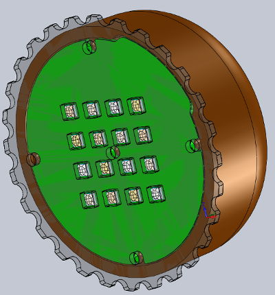
I exported the final PCB as a STEP model. I imported this model in Solidworks to confirm that my integration would be successful.
Making a unusually shaped 2-layer PCB on the Modela
The first step was to create my PNG files. Extra care need to be taken to make sure that a misalignment won't happen when you flip the board. To keep everything
centered I designed a square around my PCB in Altium. I exported that square at the same time as my Outline layer.
In GIMP, I processed the images up to the point where I had:
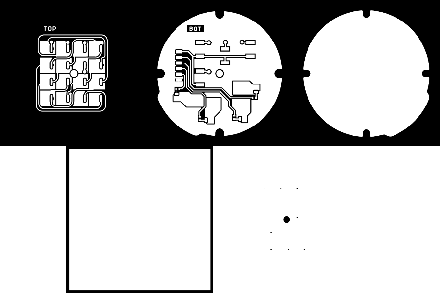
(For all the details, please refer to From Altium to the Modela (tutorial))
When I loaded my Hole file in the Fab module I realized that my vias were too small. None of the available endmills could make them. I decided to skip them; it's easy enough to manually drill 8 holes.
Summary of the steps:
- Mount PCB, zero XYZ
- Bottom face traces
- Box cutout (square outline)
- Flip the board, adjust the 0
- Outline cutout (unusual shape)
- Middle hole
- Top face traces
- Manual via drilling
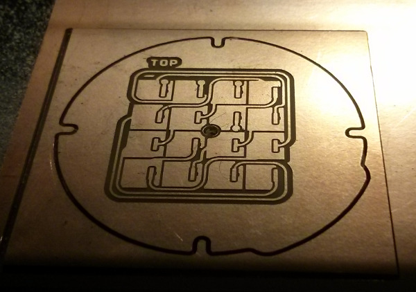
Now let's look at some images. Here's the PCB after step #3. Please note that although it looks like the unusual outline was cut, it's only the top copper that's milled (and not all the way through the fiberglass).

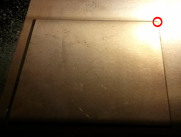
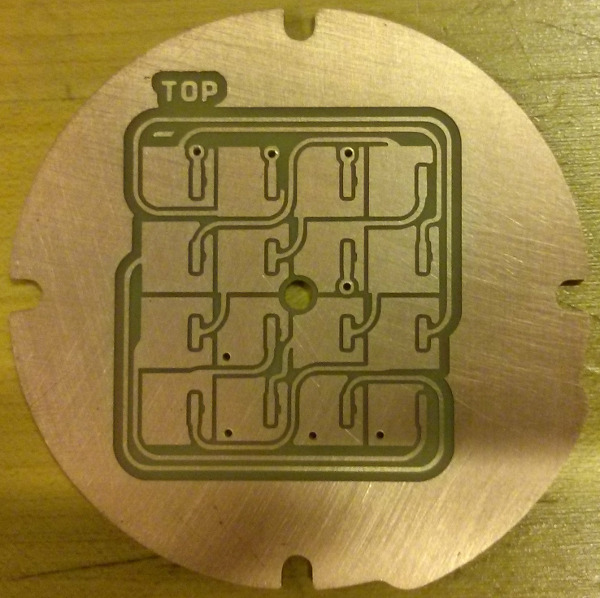
On the next picture you can see the board once it was flipped (right after step #4). In my PNG the Box outline was a square. Milling that profile created a round corner (circled in red). This prevented having a perfect
alignment. Next time I need to add a mouse bite to my image file.
This is after step #7:
I cleaned the PCB with abrasive wool. I manually drilled the hole with a 28mils drill bit. The alignment is (almost) perfect. Only one via has a partial breakout. There is no doubt that I can use this PCB.
Assembling, programming and testing the first prototype of the LED lamp
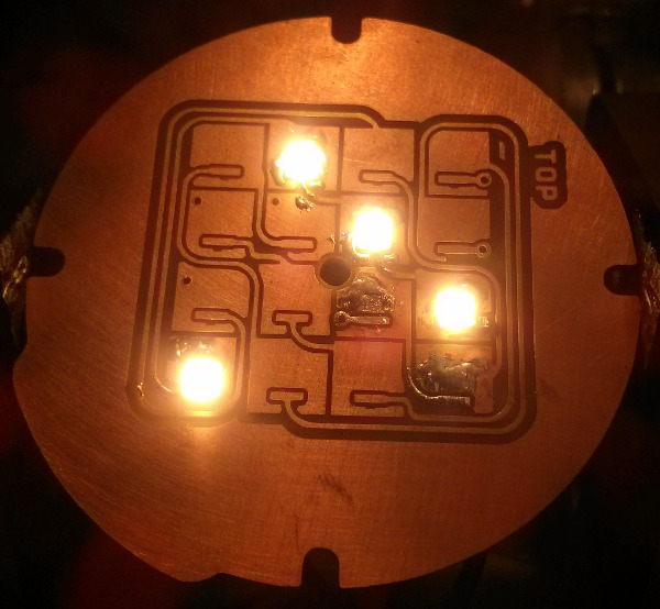
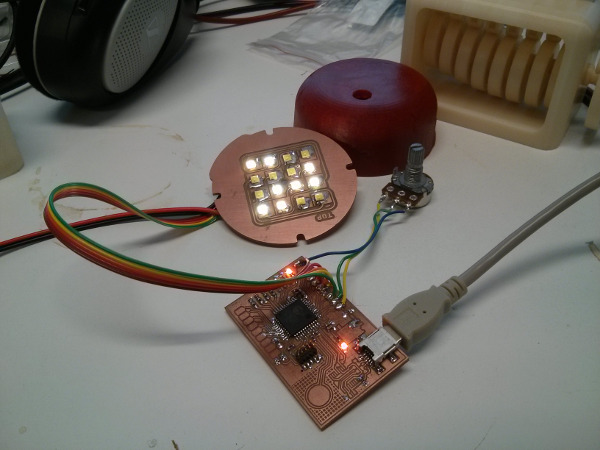
To make sure that my design was functional I started by soldering one string (4 LEDs, one power resistor, 1 MOSFET and its gate resistance). The next picture was taken with only 3 LEDs ON (one
was shorted, I fixed that after). The board was powered at 18V. I applied a PWM on the MOSFET with a function generator. If you look at the oscilloscope you can see that it's a really small duty
cycle (~10%) and yet it's really bright. Good!
It's next to impossible to take good pictures of bright lights (at least with my limited photography skills). To give you an idea when I took the next picture the LED lamp was the only light source
in my office… and my camera opened the shutter for only 1/1176s!
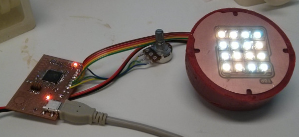
Now that I knew that I had some functional hardware I decided to link the LED board to the PSoC dev board I made in Week 6. I added a potentiometer to control the intensity (the ADC value is the duty
cycle of the PWM). PSoC are awesome for quick prototyping. It only took me a few minutes to modify my "CapSense binary counter" code and I had a functional LED dimmer. The capacitive button turns it on or off.
Here's the graphical "code":

And here's the main C code: main.c.
The FSM is ready to support more states. It will be easy to add individual color adjustment.
Here's a picture of my test setup. Two of the 4 strings were enabled.
Now that the last two led strings are debugged (it's easy to get tiny shorts when you solder SMT LEDs on a PCB that doesn't have a soldermask) I tested the fit in the enclosure.
I changed the ADC to PWM function from linear to gamma. It gives a more linear feeling as our eyes do not react to linear increments of light. More details can be found on this page.
The code is here: main2.c
I had to change of one the LEDs as it was flickering. I suspect that it got damaged by one of the tiny shorts I mentioned earlier. Always be careful with the cheap un-protected PCBs! At maximum PWM (90%) the board draws 850mA at
18V (15.3W). Without the heatsink it can quickly overheat. For your information, even at 1% duty cycle it's annoying to look straight at the LEDs...
As I really like what I've got so far I think I'll design a better PCB and have it fabricated by a PCB fab house. It will allow me to do a much better thermal management and to get a more integrated product.
To Do:
- Design capacitive slider
- Program better user interface (that includes color change)
- Integrate everything in the enclosure, add logic power supply
- Modify the case to allow planar construction of the capacitive sensors?
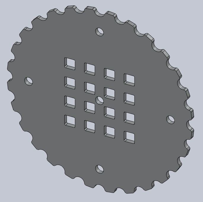
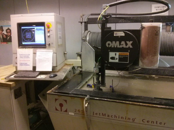
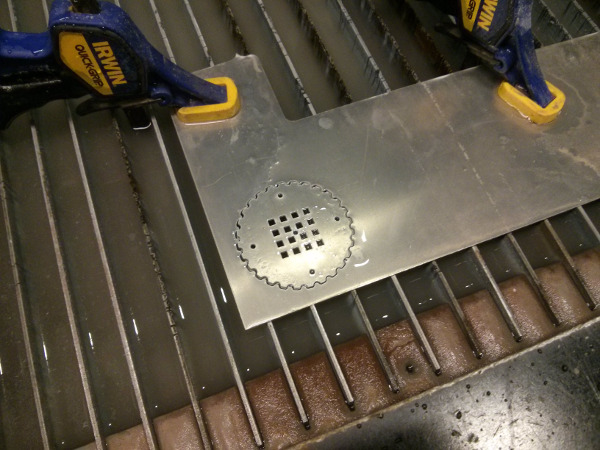
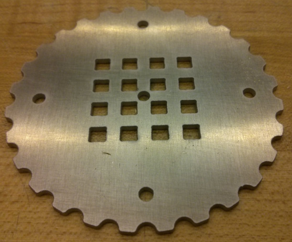
Water jet cutting: LED aluminum heatsink
I wanted to use the waterjet cutter to make the aluminum heatsink of my LED lamp. I used a scrap of 1/16in 6061 aluminum that I found in the shop.
Tom trained me. The steps below are mostly for me, as a reminder. Do not use this machine without getting trained!
- Load DXF. Make sure that your design takes into account the 30mils tool diameter.
- “Clean” PART. It will join all the gaps. Clean up to the point where no gaps have to be joined.
- Right click on “Quality”, select all, set your level (3)
- All the lines that will be cut are now purple
- In the “Lead I/O menu”, set Auto path quick. Confirm that the software “understood” your part
- Click on “Path”
- Click near origin
- At this point, the pre-processing of your file is done.
- Go through the checklist that’s printed on the machine (enough abrasive material, open water valve, …)
- Place your material on the bed. Clamp it down.
- Move head (jog) close to your zero
- Manually zero the Z axis. When it touches the material, lift it half a turn (remember to compensate for the slack)
- Lock Z axis
- Zero the X and Y axis to the 0 of your part. Do it on the machine (by jogging it into position) and in the software
- Adjust the water level to be ~1in over your part
- Start machining, wait for completion
- Lower the water level, clean your mess, close the water valve
My part took only 2 minutes to cut. The machine estimated that it cost around 6$. Quick and cheap!
Programming the BLDC driver
Actual state of the project:
- Functional onboard USB communication (I can send data to a serial terminal)
- I can read the quadrature encoder and the Hall effect encoder
- I have a lookup table that can output the right bridge signals (PWM and fixed levels)
- 5 out of the 6 PWM signals are functional. I need to rewire PWMH2 as I can't disable the SWV pin (although the datasheet says I should be able to…)
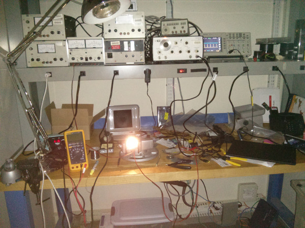
Here's a picture of the actual setup. All the test clips are going to a Logic16 logic analyzer.
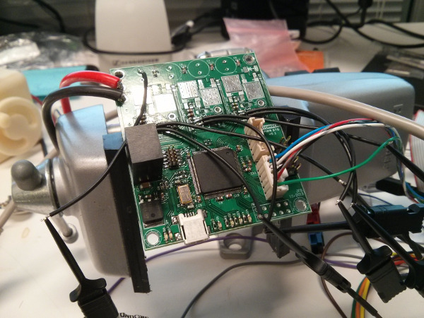
The next steps are to fix the PWMH2 problem and solder the power section.
Final Project Update
Keeping track of the evolution of the Dishpenser:
Wikipedia has plenty of good information on dishwashers:
- "Unlike manual dishwashing, which relies largely on physical scrubbing to remove soiling, the mechanical dishwasher cleans by spraying hot water, typically between 55 and 75 °C (130 and 170 °F) at the dishes, with lower temperatures used for delicate items. A mix of water and detergent is circulated by a pump. Water is pumped to one or more rotating spray arms, which blast the dishes with the cleaning mixture. Once the wash is finished, the water is drained, more hot water is pumped in and a rinse cycle begins. After the rinse cycle finishes and the water is drained, a heating element in the bottom of the tub heats the air to dry the dishes."
- "Unlike a residential dishwasher, a commercial dishwasher does not utilize a drying cycle (commercial drying is achieved by heated ware meeting open air once the wash/rinse/sanitation cycles have been completed) and thus are significantly faster than their residential counterparts. Washing is conducted with 65-71 C / 150-160 F temperatures and sanitation is achieved by either the use of a booster heater that will provide the machine 82 C / 180 F "final rinse" temperature or through the use of a chemical sanitizer."
- "Most consumer dishwashers use 75°C rather than 83°C for reasons of burn risk, energy and water consumption, total cycle time, and possible damage to plastic items placed inside the dishwasher."
- Source: http://en.wikipedia.org/wiki/Dishwasher
Wikipedia also has an interesting video of a clear case dishwasher:
Looking at this, how can we expect to get clean dishes?!?
Ideas/specs/details/random:
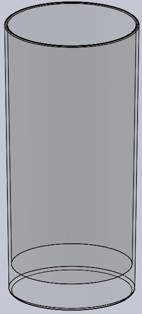
- Found good glasses at Target. Only 4$ for a pack of 4. Here's the CAD model I made:
- The outer diameter of the glass is slightly smaller than 3". I can use 3" pipes for the barrel.
- My glasses are 6" tall, I'll need a minimum of 12*6" = 72" (6ft) of pipes. 7ft is more realistic.
- On McMaster, PVC and ABS pipes are rated for only 140F (60C).
- To get > 180F I need Thick-Wall Light Gray CPVC pipes (53$ for 2ft) or aluminum pipes (28$/ft)
- Aluminum is Generally Recognized as Safe (GRAS): http://www.aluminum.org/Content/NavigationMenu/TheIndustry/HealthSafety/default.htm
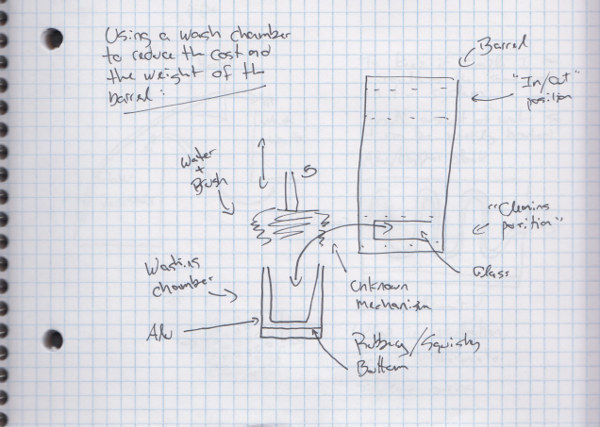
- It might make sense to wash in a separate room to keep the barrel cost down. It would also allow brushing the outer walls of the glass.
- Soap is mostly used to degrease. Glasses are not typically greasy. I might be able to use only brushing and (really) hot water.
- I can easily machine linear sleeve bearings similar to these McMaster Washdown Pillow-Block Linear Sleeve Bearings for really cheap. UHMW can withstand up to 180F.
- Nylon can also be foodsafe and heat resistant
Some rough hand sketches:
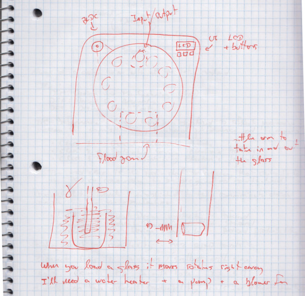

The next image presents a first attempt at CADing the brushing mechanism:
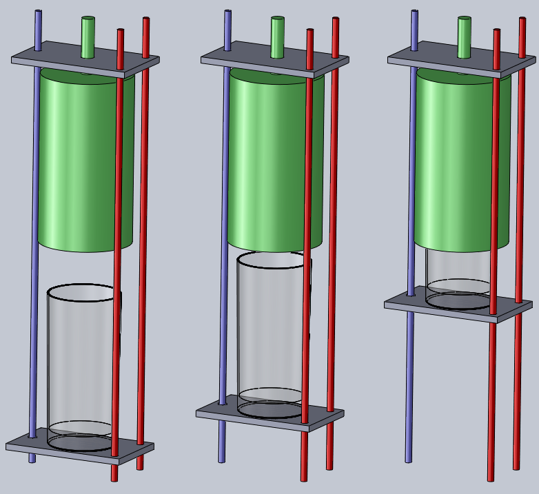
The red parts are simple un-threaded rods used for support and guiding. The blue rod is threaded. The green part is a rotary brush.
Imagine a belt linking a motor (not drawn), the blue rod and the green axle. This motor will make the brush spin and the platform
(bottom grey part) move up and down.
For a simple system I can avoid soap and recirculate water. Glasses are not usually covered in putrefied food… the water should stay clean enough.
I will need one pump, one heater and some tubing and fittings.
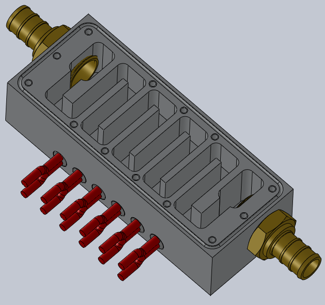
Here’s my first attempt at designing a block heater around 1/2in NPT fittings and Amico 10x60mm 120W heat cartridges:
Although I completed the CAD, I wasn’t satisfied. It’s not symmetrical, the hole pattern is irregular, it’s only 240W with no possibility of adding extra elements,
the elements are too close to the water input (safety hazard)… I don’t like it. Back to the drawing board!
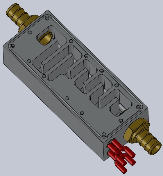
Here’s my second take on the design. I found some 100W 8x40mm cartridges on Amazon. I can get as much as 600W; that should be enough.
This time I’m pleased with the design!
To make it, I’ll need:
- 2x McMaster #3528T23: Brass Barbed Fitting for Drinking Water Straight for 1/2" Tube ID x 1/2 Male Pipe Size
- 1x McMaster #8975K311: Multipurpose 6061 Aluminum 1-1/2" Thick x 2" Width x 1' Length
- 1x McMaster #8975K713: Multipurpose 6061 Aluminum 1/4" Thick, 2" Width, 3' Length (not shown on the design)
- 1x McMaster #1092T22: FDA Viton®Fluoroelastomer O-Ring Cord Stock 1/16" Fractional Width, .070" Actual Width
- 10ft McMaster #51275K88: Polyethylene Tubing for Drinking Water, 1/2" ID, 5/8" OD, 1/16" Wall Thickness
- 1x MxMaster #: Two-Flute Carbide End Mill 1/16" Mill Diameter, 1/8" Shank Diameter, 1-1/2" Overall Length (unless we have one in the shop?) Please note that I only need this for the o-ring groove and the tapped holes. Everything else will be done witn a 1/4in endmill.
- 2 to 6x Amazon #B008SA5JA0: Amico 8mm x 40mm Heating Element Single End Cartridge Heater AC 110V 100W
- 1x eBay #271210966990: Solar DC Hot Water Circulation Pump/Cooling Brushless Motor Water Pump 12V 3M
- Some 6-32 screws
- Some insulating material to wrap around it
- Thermal paste and high-temp silicone adhesive for the heaters
Next week I’ll machine a mockup in a piece of 2x4 to confirm my design.


Jean-Francois (Jeff) Duval - jfduval(@)media(.)mit(.)edu - 2013
Top | MIT Media Lab | How To Make (almost) Anything 2013 | Index
"Hidden" keywords: Jean-François Duval, JFDuval, Jeff Duval, PCB, Dishpenser, MIT Media Lab, Biomechatronics, Electronics, Robotics, DIY, Hack, Hacker