Week 5: Electronics Design
Objectives
Create the traces for the echo hello-world board, add (at least) a button and LED (with current-limiting resistor), check the design rules, and make it
Designing the Schematic in Eagle
This assigment was an expanded version of the one from week 2. During the Electronics Production week, a designed schematic was provided and we had to fabricate the PCB corresponding to the schematic. For this week, we had to do the same thing again, but now we also had to design our own schematic.
Prior to this week, I had no experiences with PCB desing. I had seen other people using Eagle for PCB desing in the past, but I never used the software myself. Hence, the first couple of days during this week were spent learning Eagle. I followed the Sparkfun Eagle tutorial to learn the basics of the software.
I first recreated the schematic for the Hello World board, and then I added an LED and a button.
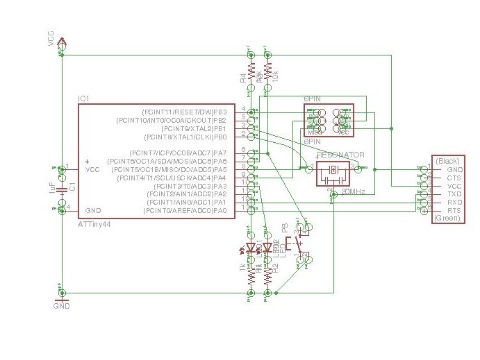
Then I began the process of routing the traces for the actual board file. It took me far longer than I expected to finish the routing process for two reasons. First, I did not know what resources were available to me in the software so I had to become acquainted with that. And second, solving the actual puzzle of routing the traces in a way that they don't overla was a nontrivial and time-consuming task. I went through 4 or 5 iterations until I arrived at a solution that required no jumpers. I also tried the Eagle's autoroute functionality but it was completely usless. With the default settings, it gave results that required between 3 and 6 vias, and with the option for a single-layered board, it could not finish the calculation.
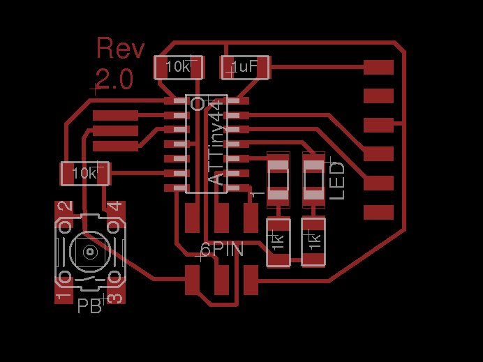
After finishing the desing of the circuit and the routing of the traces, I exported the board file as a .PNG image in monochrome format. Then, in Pinta Image Editor I created a monochrome frame for the board and saved it also in .PNG format. Now I was done with the new part of the assigment. I had the traces file and the dimensions file as PNGs and I was ready to mill my board.
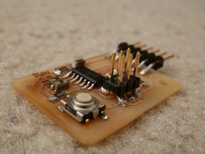
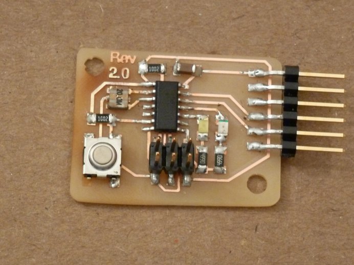
The rest of this process was the same as the one from week 2. After going through the milling and stuffing phase, I had my new board complete.
In addition the LED and Button i also added 2 mounting holes to the board. I did not know how to do that in Eagle so I added those in the image-editing software and saved them as part of the outline file.
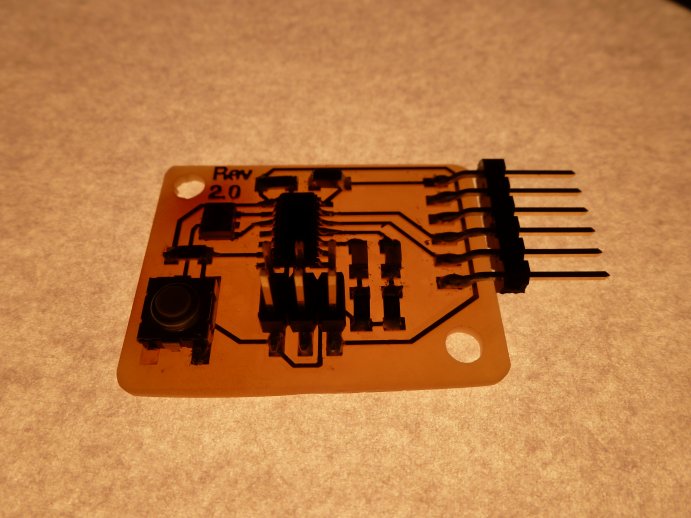
A lesson I learned subsequently is that my FTDI should not be attacheed in the way I have it on the board. What I should have done instead was cut the board a little wider, such that the FTDI header rests fully on the board