Week 03
Computer-Controlled Machining
Make Something Big
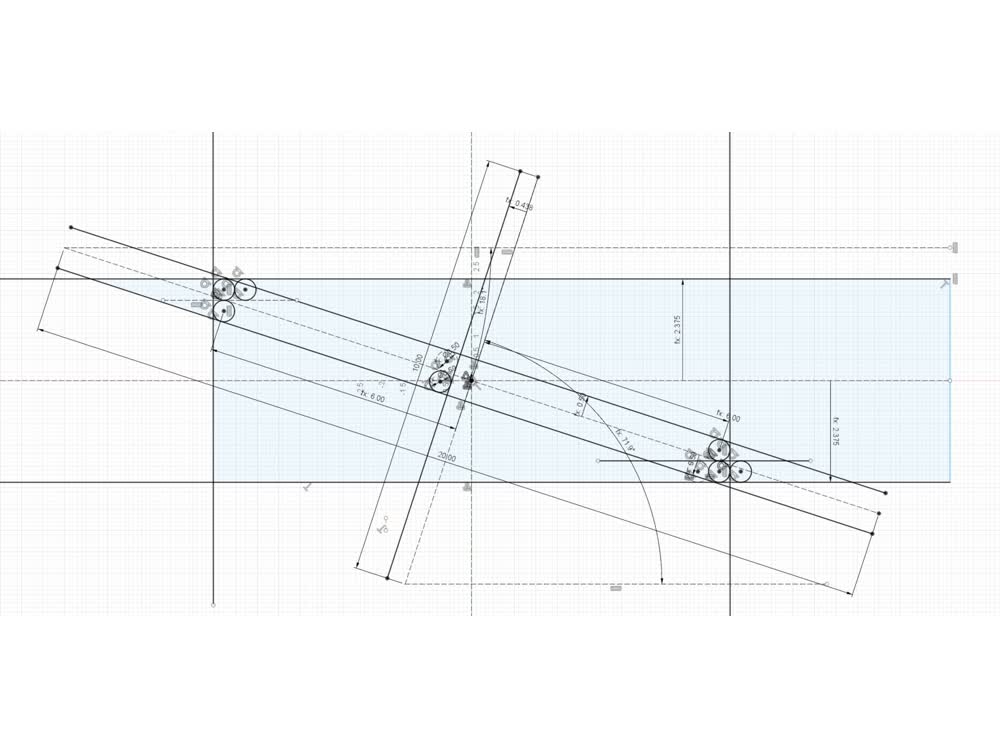
For this week's assignment, "Make Something Big", I decided to make something long. Specifically, I made a beam from a 4' x 8' sheet of OSB using a modified version of a type of Japanese scarf joint known as kanawa-tsugi. The kanawa-tsugi
relies on a sandwich of two distinct profiles that together create a geometry that interlocks with itself. I find that very satisfying. There is no "positive" or "negative" side of the joint because each side is identical. See a model of this
joint below created by The Joinery.
Source: The Joinery
The first step was to parametrically sketch the joint geometry in Fusion 360. Once I had this set, I moved the design over to Rhino. I'm still getting the hang of Fusion and I find that for quickly copying and moving around geometries, Rhino
is much more straightforward. In Rhino I also added holes along the length of the beam sections just to serve as registration keys for gluing up the kanawa-tsugi sandwich. In addition to the pieces for the beam sections I also milled out a
strip at the correct width to be used as keys for the registration holes as well as wedges that I would later use to drive the joints together.
 Constrained sketch of joint profiles.
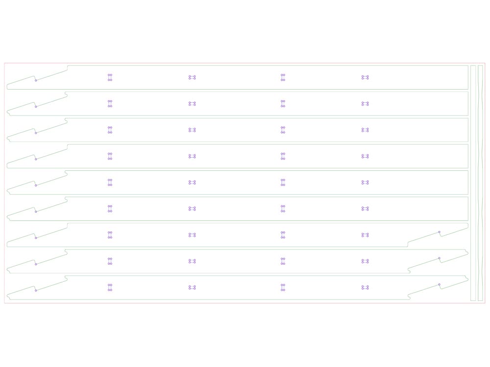 Maximizing use of OSB sheet.
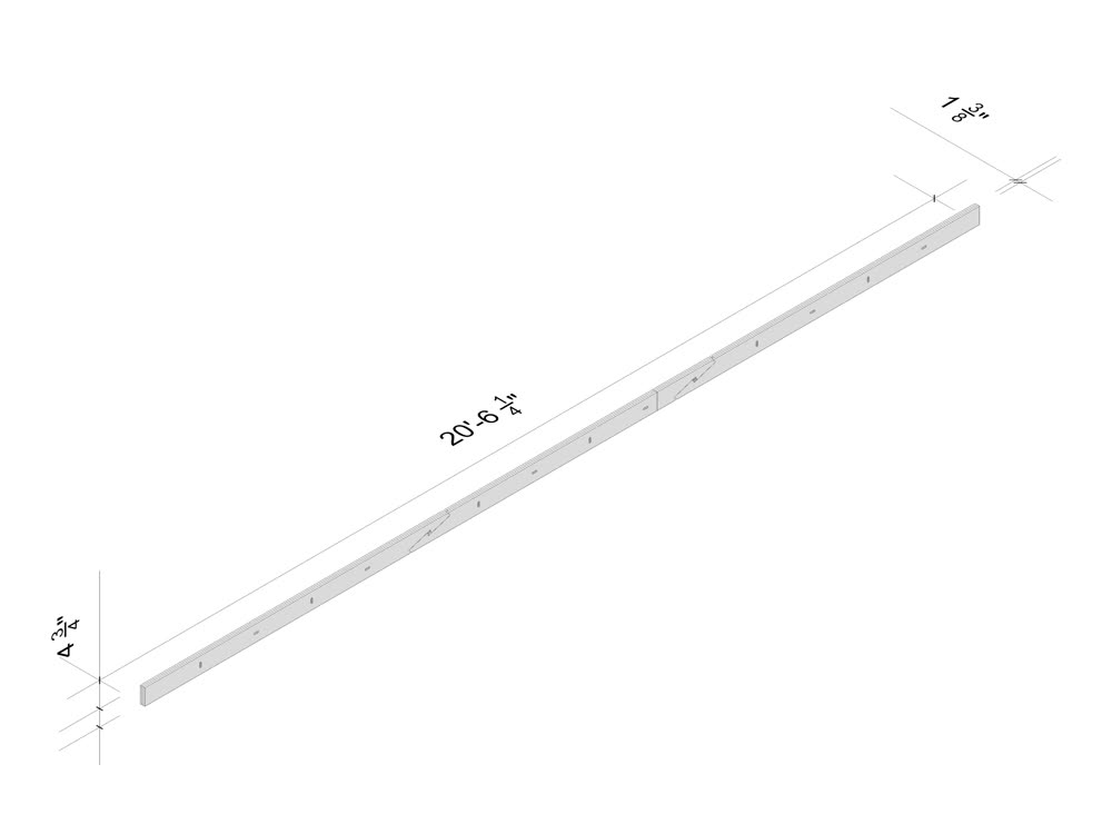 Full beam in Rhino with dimensions.
Once the geometry was set it was time to lay it out on the stock and import it into MasterCAM. I used three toolpaths: one for drilling out the internal corners with a 1/4" drill bit; one for clearing out pockets with a 1/4" downcutter; and
one for cutting out the parts with a 3/8" compression bit. Overall the milling went well though I did have some issues with parts that weren't all that small coming loose. I think a more agressive onion skin or tabs should have been
incorporated.
Video of three part milling process.
After milling and cleaning up the parts a bit I laminated the sections of the beam using the registration keys previously mentioned to make sure everything was aligned. I was initially hoping to glue up all three sections at once but this
proved to be a bit ambitious and I ended up gluing up two together and one on it's own.
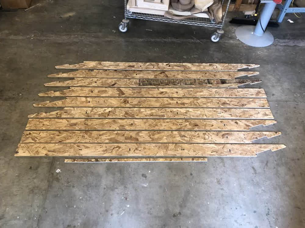 All of the parts.
 Key in place during glue-up.
Time to assemble! I laid out the beam sections keeping everything roughly level and then used a clamp to drive wedges into the joint from both sides. OSB has some downsides, one being that it does not like to be subjected to forces on-end
as
it tends to delaminate. There was definitely somewhat of a gap but I'm actually surprised by how well the joints when together. I didn't include any kind of tolerance in the joint geometry because I figured that I can't really predict if
I
will end up with too much material or too little and either way the OSB has enough give that I can compress to some extent to create a tight joint. Probably not the best practice but in this case it worked out.
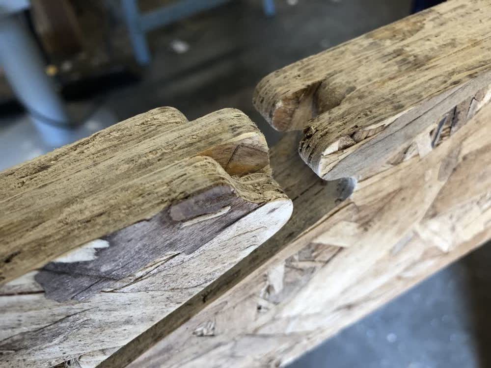 Detail of joint before assembly.
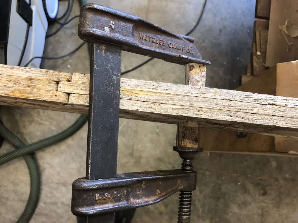 Driving together joint with clamp.
 Assembled joint.
With the joint assembled I brought it outside for some load testing. The beam could more or less support it's own weight, but the addition of flanges would have made a big difference. It constantly looked like it was going to fail due to
lateral torsional buckling. Ultimately the failure happened when part of the joint geometry just ripped off under the weight of my body.
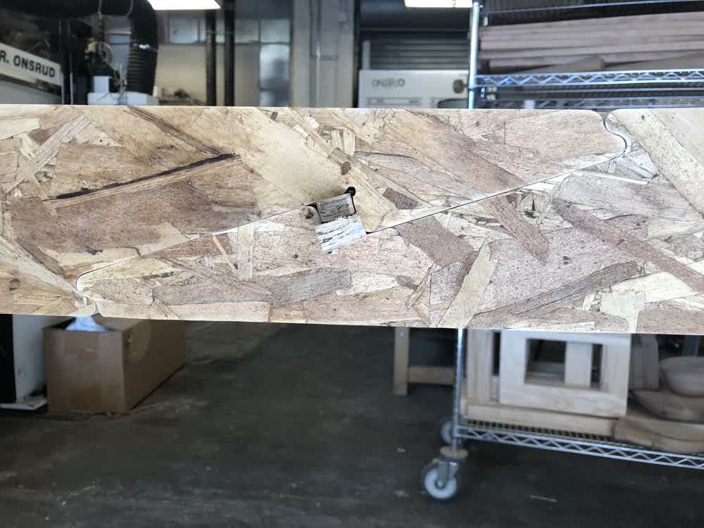
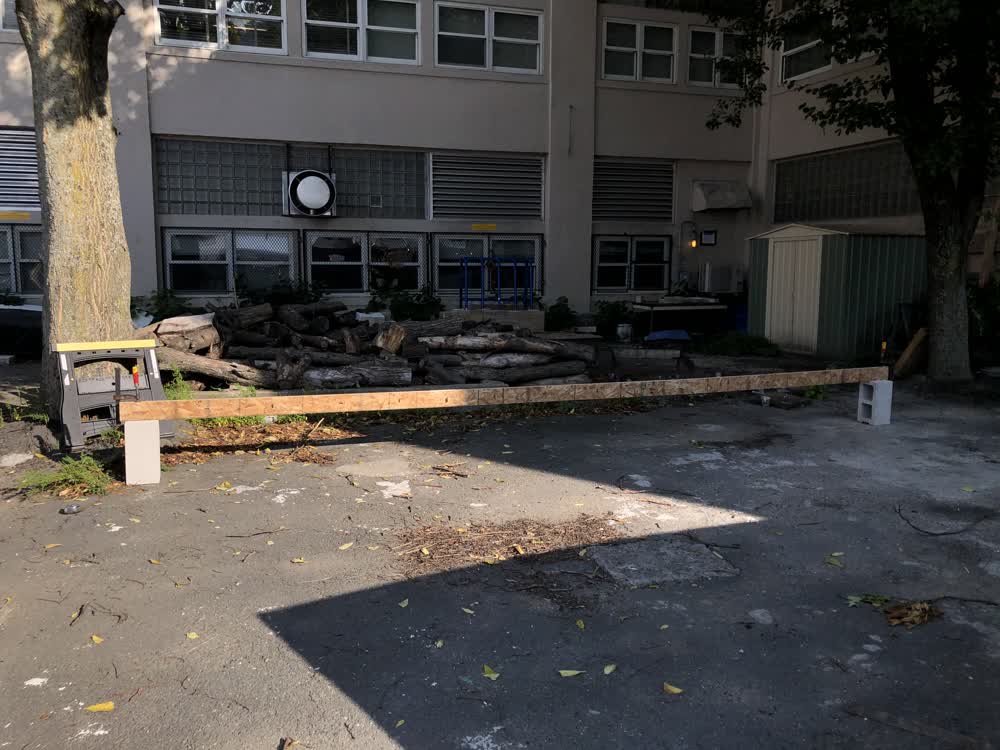 20 foot span (with some sagging).
Testing to failure.
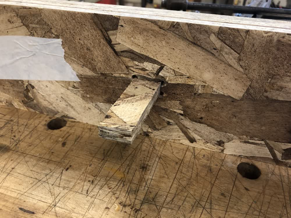
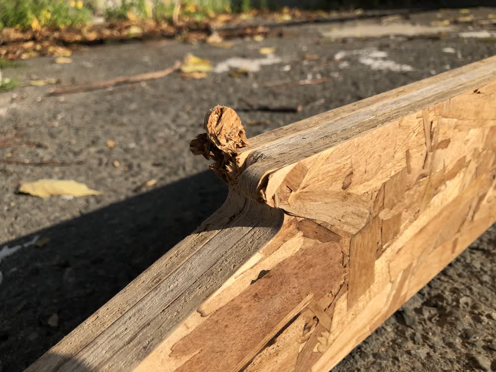 Point of failure on the joint.
After testing the beam to failure I figured it would be a shame to just put the OSB in the trash so I assembled a quick workbench stool for a little workshop I have set up in my basement.
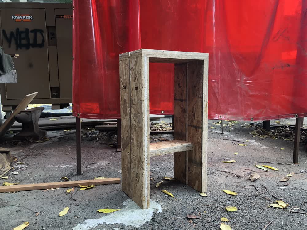 Workbench stool.
Files: 200920_kanawa_tsugi.f3d