Week 08
Input Devices
Take One
Last week I made my board using the SAMD11C. This week I decided to try out an AVR chip so I could compare working with the two frameworks as I move towards my final project. I decided to try to reinterpret Neil's step response board using the Attiny412. Mistakes were made.
The first problem with my first attempt was that I failed to supply power to the 412. This was due to not explicitly labeling GND and VCC on the 412 in my schematic in Fusion.
 Original schematic.
 No power to 412.
This was easily fixed with a little surgery.
 Adding power to the 412.
Once my board was powered, I was able to use the 412's UPDI pin to successfully flash programs to the board, however, when opening a serial miniterm, I was getting no feedback from the board even when running Neil's echo program for the 412,
which I knew should be offering feedback. After a lot of troubleshooting I went to the issue tracker for help. I had been under the impression that both programming and serial communication could happen over the UPDI pin on the newer Attinys.
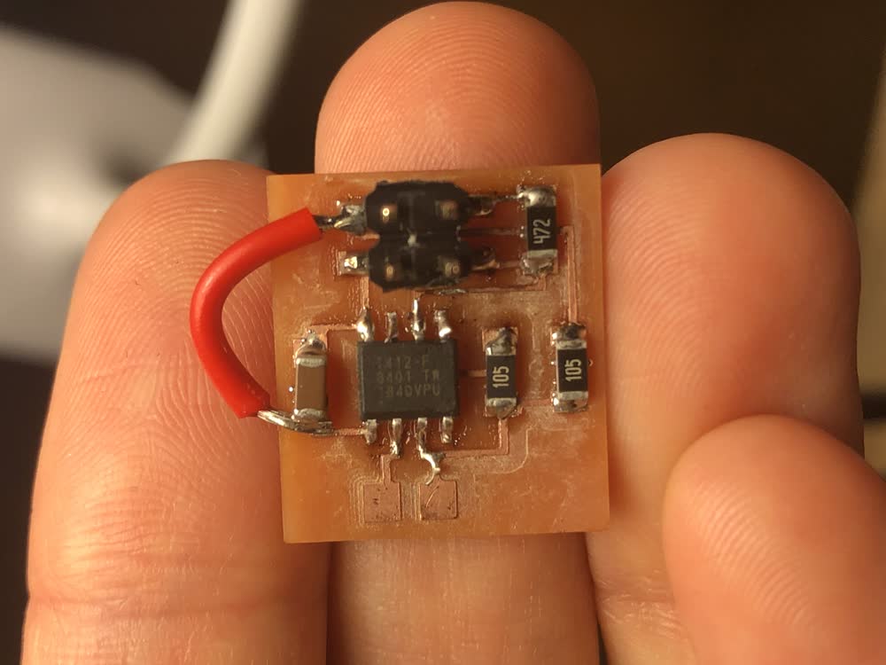
Turns out this is not the case, as Anthony explained. I needed to break out pins PA1 and PA2 to communicate over the serial port. I first attempted to do this just with a bit of surgery, adding some wire directly to PA1 and PA2.
 When debugging turns the board into a bug.
In theory this should have worked but I still wasn't getting feedback over the serial port. I decided it was time to scrap this board and start fresh. In addition to adding power to the 412 and breaking out PA1 and PA2, this time around I
also changed the design of my capacitive sensor follwing the instructions here. Given the difficulties getting serial communication to happen, I thought it might make sense to
simplify things a bit.
Take Two
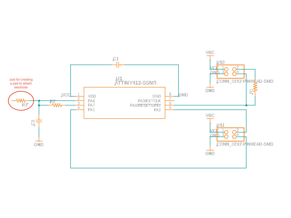 Updated Schematic.
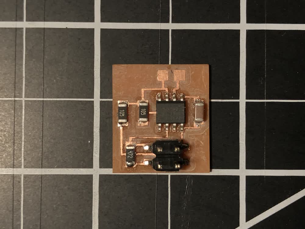
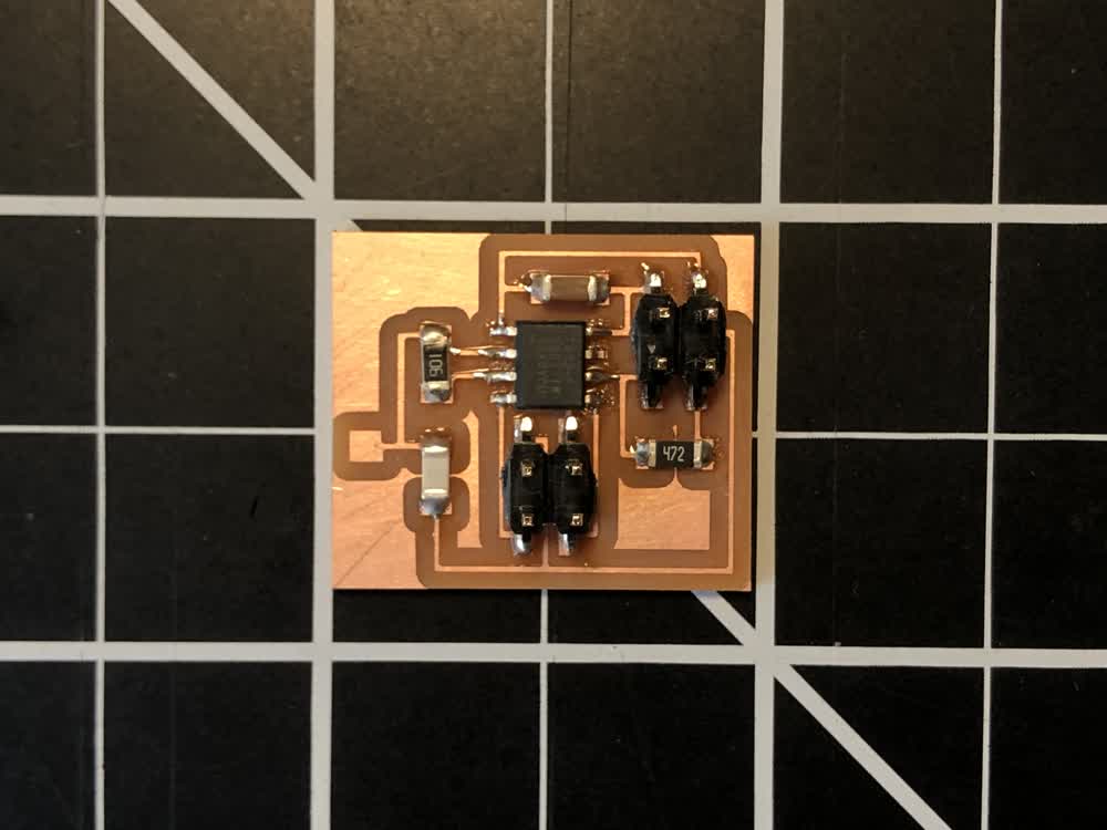 New board.
The code I used is just an adaptation of an example sketch provided by the CapacitiveSense library for Arduino.
#include

/*
 * Adaptation of CapitiveSense Library Demo Sketch
 * Paul Badger 2008
 */

CapacitiveSensor   cs_1_0 = CapacitiveSensor(1,0);
// 10M resistor between pins 1 and 0, pin 0 is sensor pin
#define max_buffer 25

void setup() {
   Serial.swap(1);
   Serial.begin(115200);
   cs_1_0.set_CS_AutocaL_Millis(0xFFFFFFFF);

   }

void loop()
{
    long start = millis();
    long total1 =  cs_1_0.capacitiveSensor(30);

    Serial.print(millis() - start);
    Serial.print("\n");

    Serial.print(total1);
    Serial.print("\t");

    delay(100);
}
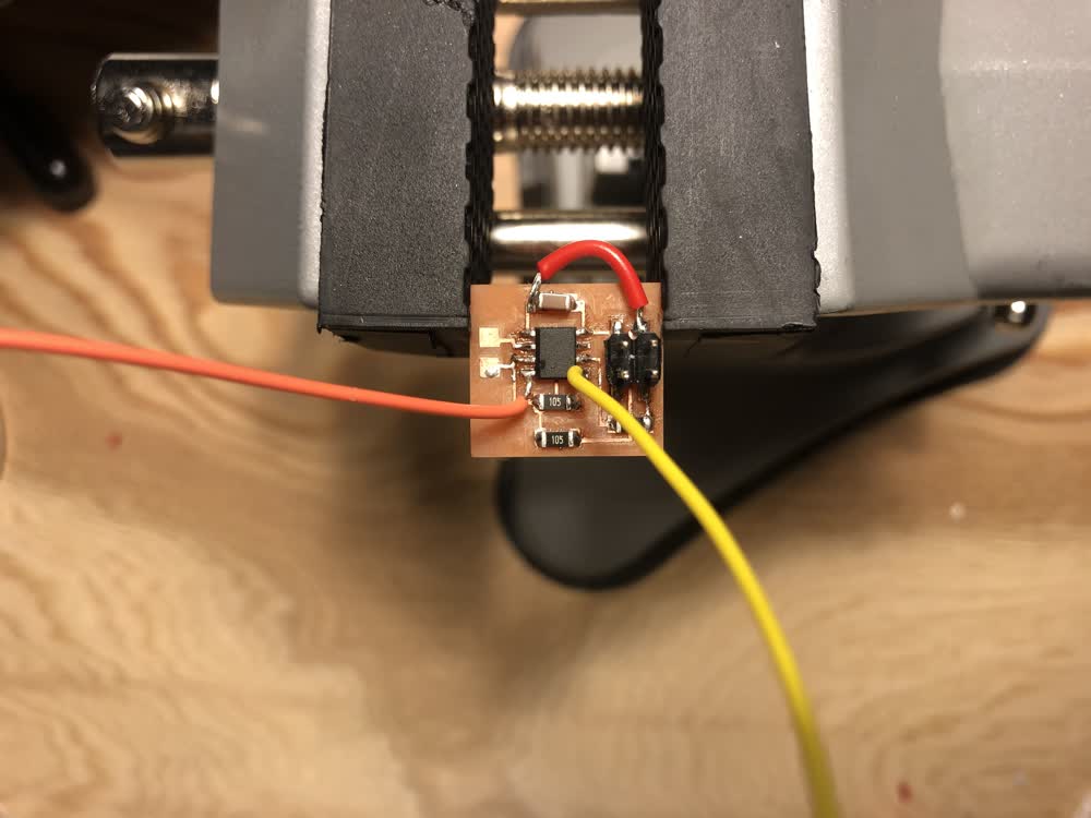
Once I added an electrode, in this case an alligator clips with wire, I was in fact able to get some readings! However, something was a bit strange with the readings I was getting. My board included a 10M resistor between the send and receive
pins for the capacitive sensor. The larger the resistor, the more sensitive the sensor. With this size resistor I was expecting to get readings with my finger at least a couple of inches away from the electrode but in reality I was only
getting a significant change in reading when my finger was actually touching the plastic covering for the alligator clip. I'm not sure what was causing this scenario.
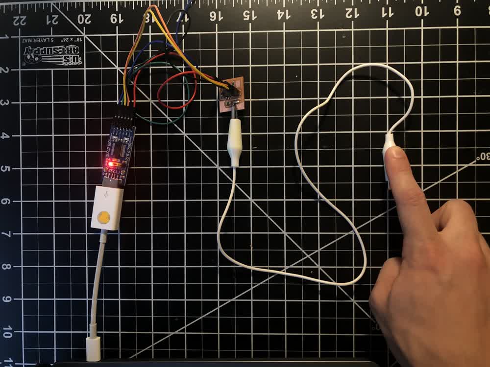 Capacitive sensor in use.
Sensor readings
Capacitive sensor in use.
Sensor readings
AVR vs. ARM
Having worked with both the AVR and ARM frameworks now, I think I will return to the ARM chips, but mostly for somewhat trivial reasons. First, I had trouble installing UPDI and I'm not totally confident in its stability on my machine.
Others on mac have been having issues as well.
Second, and more importantly, I just prefer the convenience of USB communication directly from the board over the need for an FTDI cable.
File: 201102_traces.png
File: 201102_outline.png