Week 06
Electronics Design
EDA
This week was all about learning a piece of EDA (electronics design automation) software, reworking an existing design, and fabricating it. I started by learning Eagle, which isn't really Eagle anymore but is instead fully integrated with
Fusion 360.
I had a bit of difficulty figuring out which board to to modify. I started with a modified Attiny44 board, simply because that was what was done by students in previous years and there was ample documentation. I got as far as milling the
updated board when I realized it would make more sense to make a board for a more powerful chip that might be easier to run. For this reason, I set out to make a modified version of Neil's ATSAMD11C echo board. It's kind of a shame to throw out the work I had done but it also allowed me to go through the cycle of schematic to
PCB again. Some good practice.
 Board for Attiny.
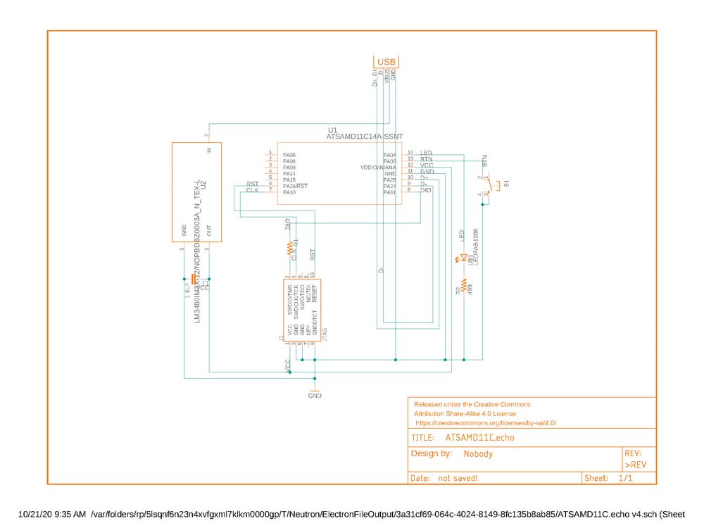
The first step was to build the schematic. I tried to follow the logic of Neil's board but it turns out I ended up wiring the regulator incorrectly. Next time I will definitely give more time to making sure the logic in the schematic is
correct. The regulator drops the 5V that comes in from USB down to 3.3V, which is within the operating
range of the ATSAMD11C. A bypass capacitor is used to filter out AC noise from the DC current and brings that to ground. I originally had it wired such that the output of the regulator was just running through the bypass capacitor without
connecting the capacitor to ground. This just blocks the DC current altogether, meaning I wasn't supplying any power to my board. Instead, the bypass capacitor needs to connect the OUT of the regulator to GND. Unfortunately, I didn't make
this correction until after the board was fabricated and I was able to test it. Zach was very helpful in explaining how the regulator and bypass capacitor actually work, and how they should be wired.
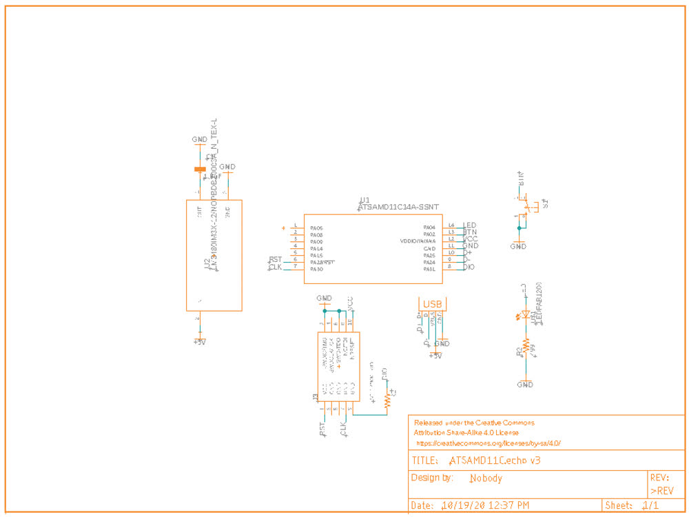 Incorrect schematic.
After setting up the schematic (albeit incorrectly), I moved onto routing the PCB. The main issue I faced here was finding the components in various libaries. I wasn't able to find the Serial Wire Debug programming header (Amphenol
20021121-00010T1LF) that Neil used on his board when I initially did the routing I used a place holder in Fusion and edited it in Rhino. This is definitely not a good practice, but it worked for me. In Rhino I was able to also clean things up
and you could also add artwork, etc. More on designing PCBs in Rhino below. Eventually I was able to find the missing part. The problem was that I was searching by inches (0.05") but the part was listed by millimeters (1.27mm).
 Unfinished routing in Fusion.
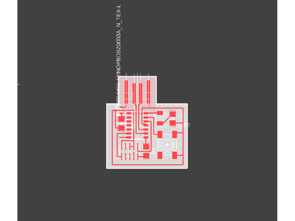
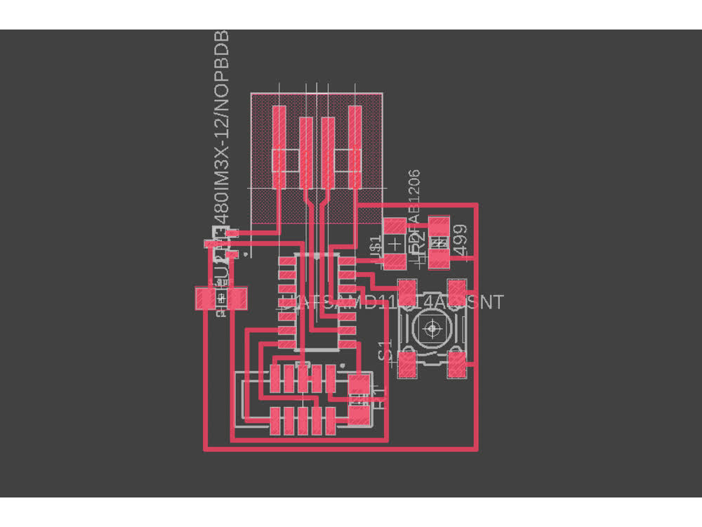
 Finished but incorrect routing in Rhino.
When I went to mill this board, everything went smoothly on the engraving but during the cutout path, the board rattled loose and was gouged by the end mill. Luckily the endmill didn't break. I also realized there was an error in this board
where two adjacent traces are too close together and ended up being connected.
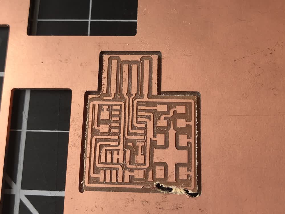 Gouged board.
I updated my settings in mods for the cutout path to decrease the stepdown from 0.024" to 0.018". The next time I cut this board the cutting sounded less strained. After making the adjustment to fix the connected traces, I milled the board.
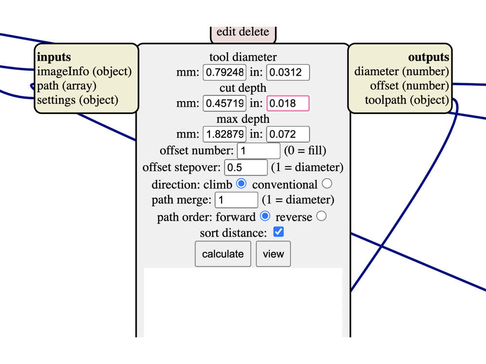 Updated mods settings.
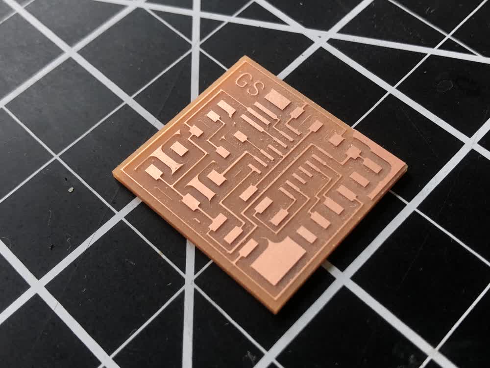
Next it was time to stuff the board. I'm starting to get the hang of the soldering. Just to reiterate, this board does not work.
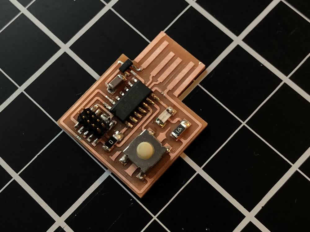 Stuffed board.
Again, this board is wrong but I was able to get help from Zach in the issue tracker, updated my schematic and routed the PCB. Now I just have to make the board so I can use it for next week.
 Corrected schematic.
 Corrected layout.
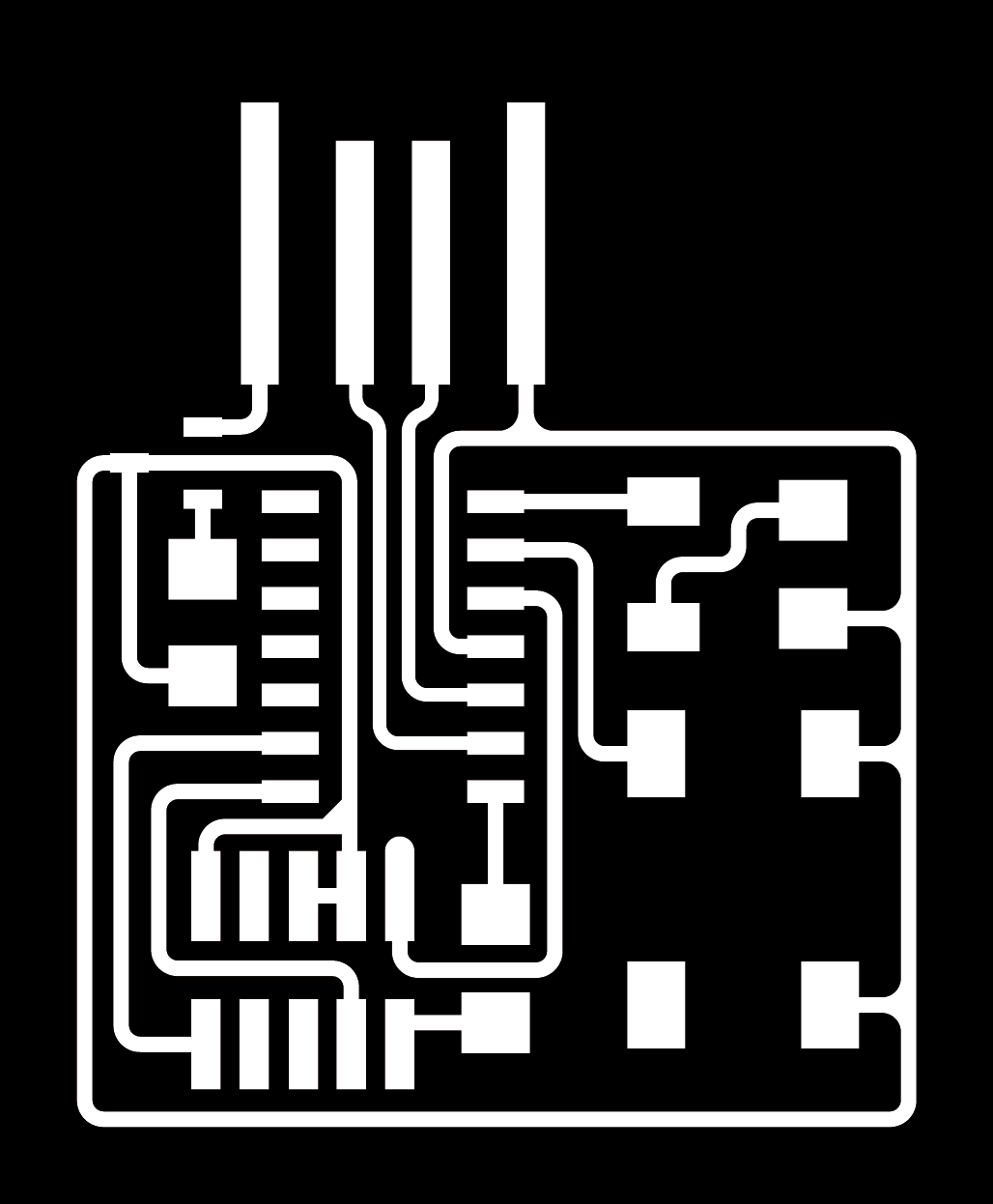
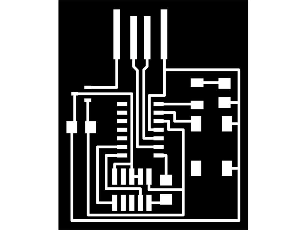 PNG ready for milling.
(Trying to) Program
To program the board, I first installed EDBG using the directions found here. EDBG allows you to program Atmel MCUs using the CMSIS-DAP protocol.
I went to the architecture shop to try to use the Atmel-ICE that is there to flash the bootloader onto the ATSAMD11C. I kept getting an error that indicated a bad connection somewhere. Of course, now I know the board was designed incorrectly,
so this was never going to work.
Circuit Design in Rhino
I found this week that it was handy to export .dxf files from Fusion in order to be able to work on them in Rhino. I find it easier to clean things up in rhino or to add artwork, etc. The problem with Rhino is that it doesn't have the
design checks built into fusion. To emulate something like the DRC I made a grasshopper script that checks the distance between lines. You can download the file at the bottom of the page.
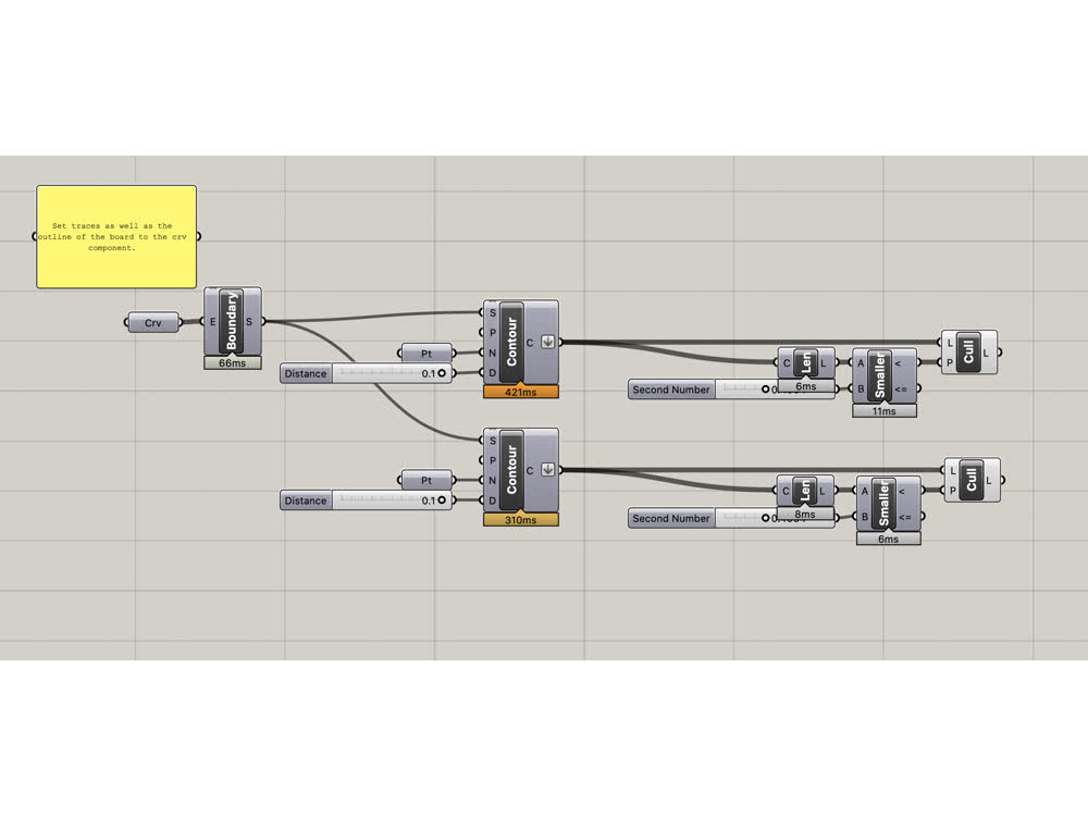 Grasshopper DRC.
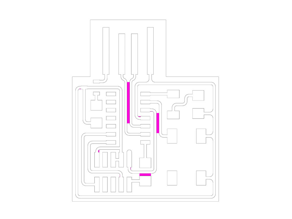 Highlighting areas between traces under 16 mil.
File: 201020_trace_check.ghx
File: 201019_traces.png
File: 201019_outline.png