Week 07
Embedded Programming
The Boards
At the very end of last week/beginning of this week, I redesigned the board I had made last week that didn't work on account of the incorrect wiring of the regulator. Below is the corrected schematic, layout and PNG for milling. This board
runs on the SAMD11C. The SAMD11C requires 3.3v so there is a regulator that drops the 5v from USB down to 3.3v. There is a bypass capacitor connecting the OUT of the regulator to ground to help prevent noise from entering the system. I've
added an LED with a 499 ohm current limiting resistor and a button. To size the resistor, I took the specs found on the product page and used the following equation: Resistance = (Supply Voltage - Forward Voltage) / Current. The
resistor is sized for a supply voltage roughly twice the size of the actual supply voltage, which is reccommended here.
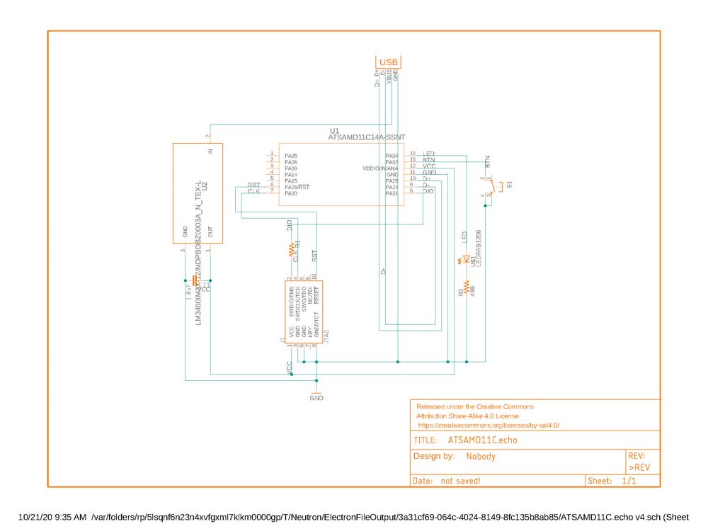 Corrected schematic.
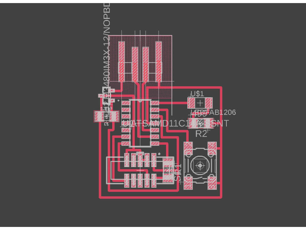 Corrected layout.
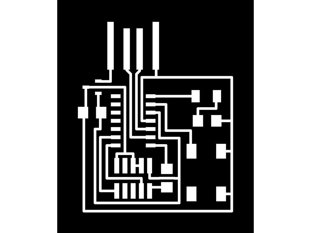 PNG ready for milling.
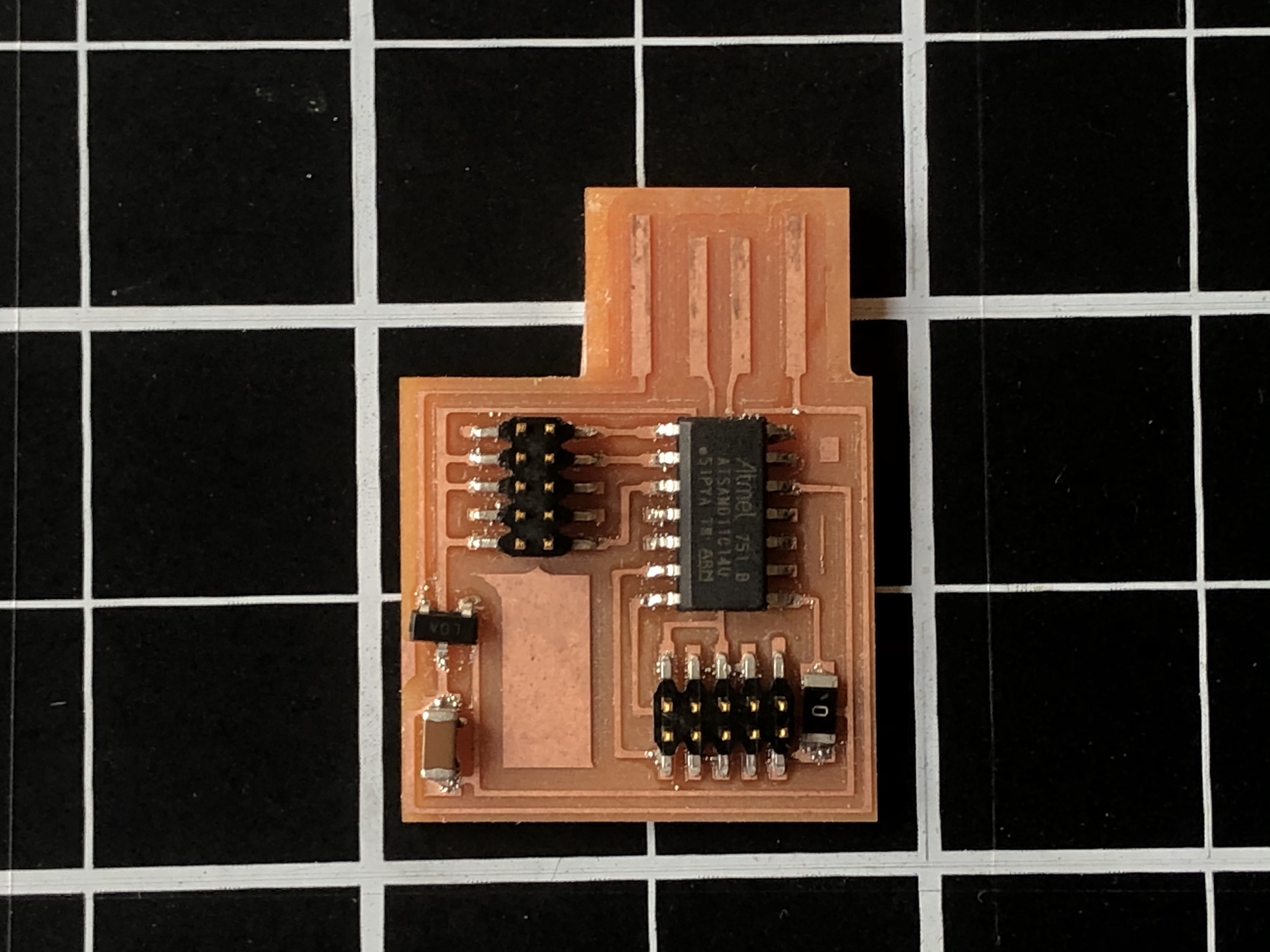
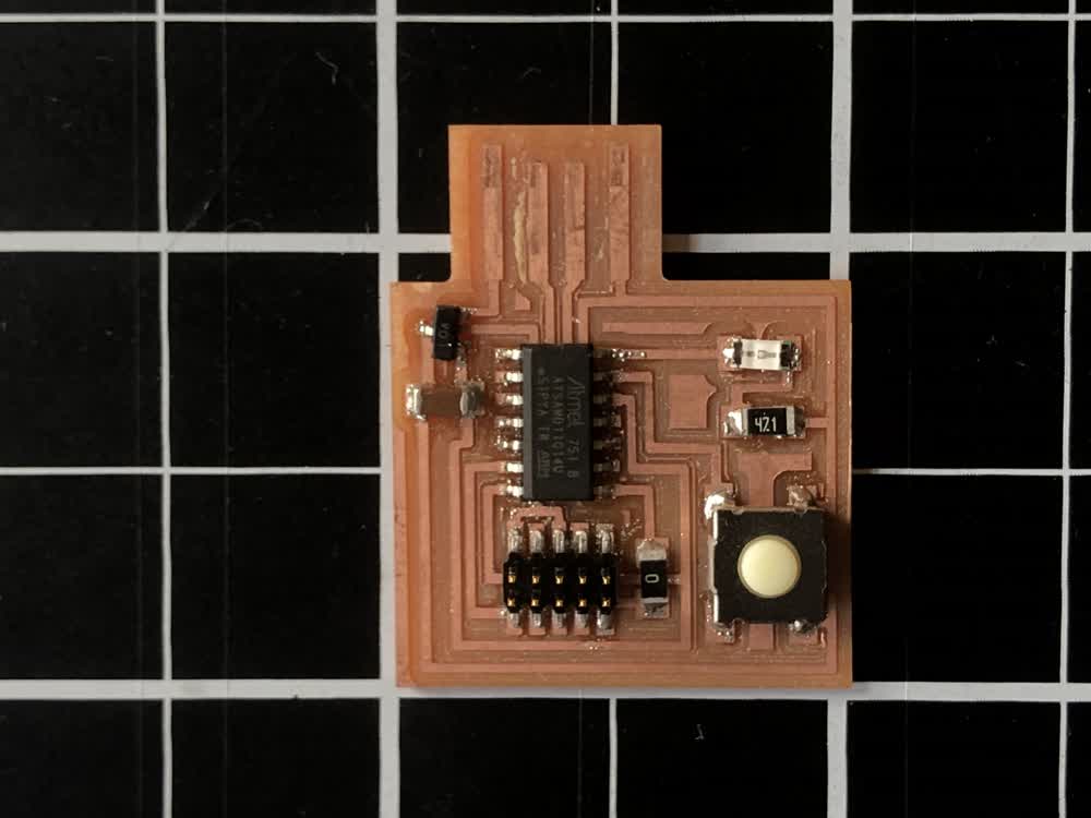 Stuffed board.
In addition to the board described above, I also made Neil's SAMD11C programmer design. Once Free-DAP is flashed to the chip you can use it to program other boards. For now I can just use the Atmel ICE in the lab but it would be convenient to be able to program boards at home. I was
able to flash
Free-DAP to the board and have my computer recognize the device but then encountered the following error below when trying to use it as a programmer: "incorrect DAP_INFO_CAPABILITIES size". I will try to resolve this in the coming weeks.
 SAMD11C programmer.
Programming
To get programming, I had to first install edbg and its dependencies. From there I could execute edbg in terminal to flash binary files to the boards. First, I used the Atmel ICE to flash the bootloader to the board. The
bootloader is a small program that enables it to read new programs you upload. It's possible to program the board without flashing a bootloader but it means that a programmer will always have to be attached to the board.
With the bootloader on the chip it was time to set up the Arduino IDE to work with the SAMD11C. This just involved going into the board manager and installing the MattairTech SAMD core for Arduino. Then it was time to program! I started by
running Neil's echo program just to make sure the board was actually working.
Very excited to see the board is working!
Once it was confirmed that the board was actually working, I wrote a program with the Arduino Libraries to work with the LED and button I had added to the board. In designing the board, I didn't include a pull-up or pull-down resistor
with
the button. Luckily, the SAMD11C has resistors built in for I/O pins and I just had to set the pin mode in Arduino to "INPUT_PULLUP". In the code below, the loop is repeatedly reading the button pin which should read "HIGH" by default
because of the pull-up resistor, and if it doesn't read "HIGH" it means the button is pressed, connecting the pin to ground. If that is the case, the "digitalWrite" function alternates state of the LED pin with a delay creating the
flashing sequence.
int ledPin = 4; // make sure to not use the sequential numbering system
int btnPin = 2; // make sure to not use the sequential numbering system

void setup() {
  SYSCTRL->OSC8M.bit.PRESC = 0; // set OSC8M clock prescaler to 1
  pinMode(ledPin, OUTPUT);
  pinMode(btnPin, INPUT_PULLUP);
}

void loop() {
  if(!digitalRead(btnPin)){
    digitalWrite(ledPin, HIGH);
    delay(100);
    digitalWrite(ledPin, LOW);
    delay(100);
  }
}
It works!
I also attempted to program the board without the Arduino libraries. The code for this is below. I was able to get the LED to flash but could not make the button responsive.
#define LED PORT_PA04

void setup() {
   SYSCTRL->OSC8M.bit.PRESC = 0;
   REG_PORT_DIR0 |= LED; // set LED pin to output
   PORT->Group[0].PINCFG[2].bit.INEN = 1; // set button pin to input
   PORT->Group[0].PINCFG[2].bit.PULLEN = 1;// set button pin pull-up
}

void loop() {
  while (1) {
    if((REG_PORT_IN0 & PORT_PA02) !=0){
      REG_PORT_OUTTGL0 = LED;
      delay(100); // delay
    }
  }
}
File: 201022_traces.png
File: 201022_outline.png