For my final project I made a machine for measuring, marking and cutting. To see how the project developed you can view my Final
Project Tracker page.
The machine can be understood in three modules: one for measuring, one for marking and one for cutting. Each of these modules is driven by a single stepper motor. All three modules are afixed to the top plate of the plywood housing.
The machine is controlled by a SAMD21E18A board based off of a schematic from Jake found here. This board is compatible with the Adafruit Trinket M0 bootloader, which
is convenient but there are only pin mappings for 6 pins in the Arduino core for this board, which is not so convenient. I broke out all of the free pins on the SAMD21E18A but ended up only needing 6 of them to drive the three stepper
motors so that ended up not being an issue in this case. All of the "inputs" to run the
machine are done in software.
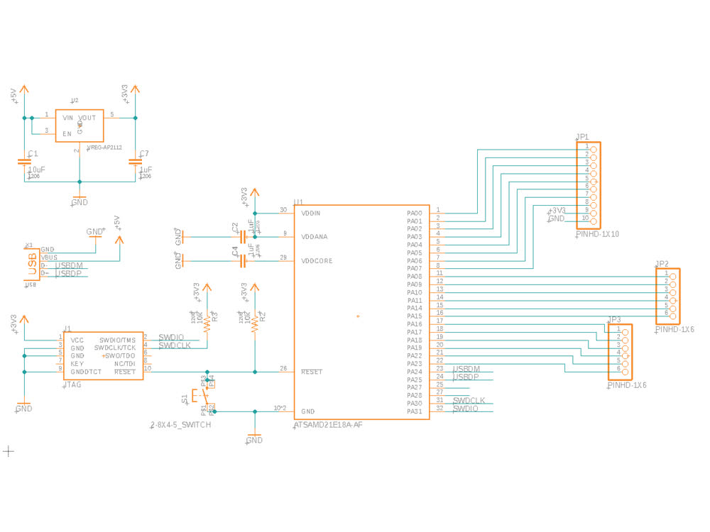 SAMD21E18A schematic.
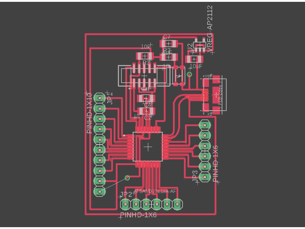 SAMD21E18A board design.
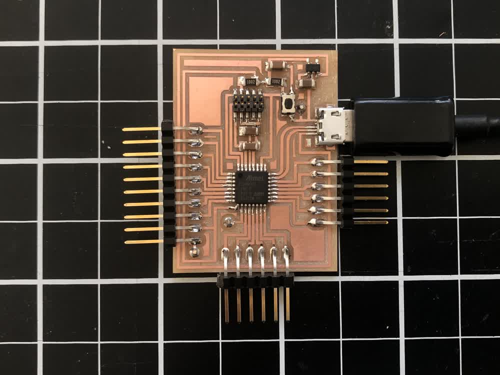 SAMD21E18A board.
In addition to the microcontroller board, I also designed and fabbed a board to house the three stepper drivers. The stepper drivers are made by Pololu and run on the A4988 chip.
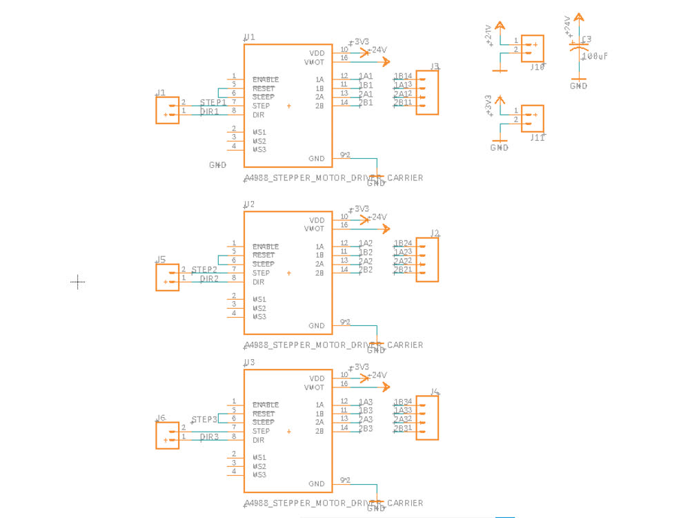 Driver holder schematic.
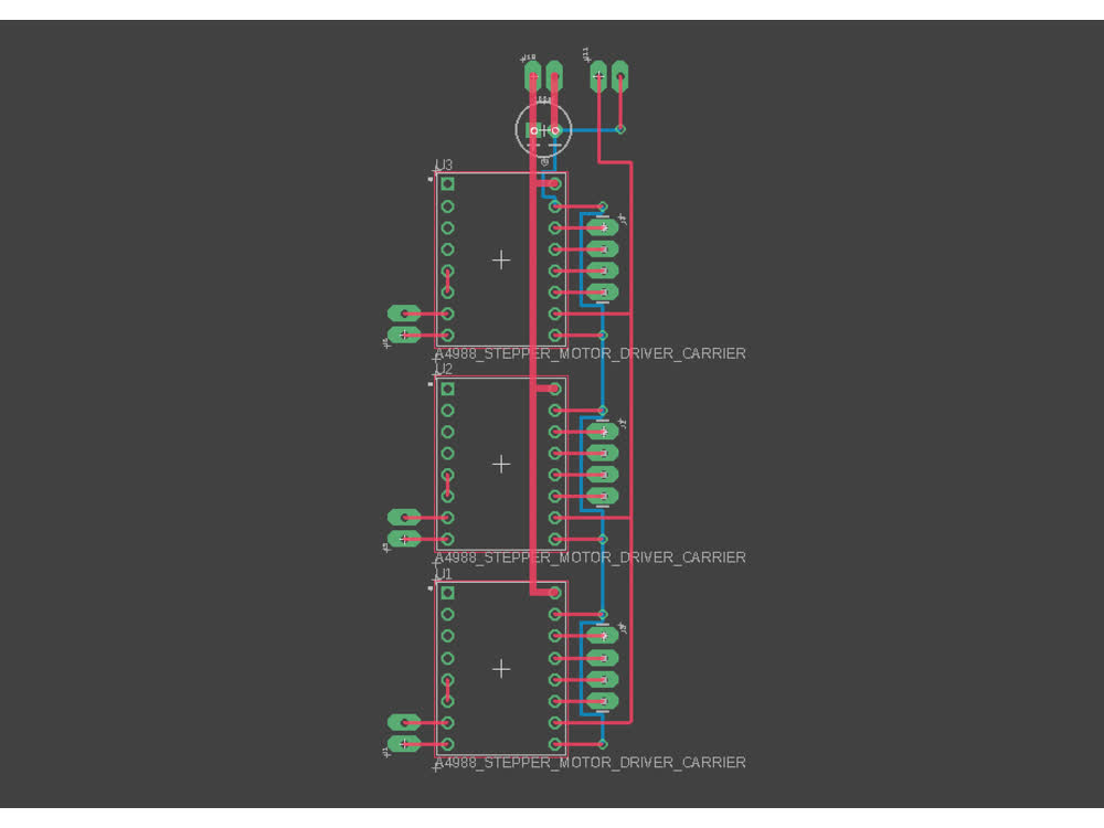 Driver holder board design.
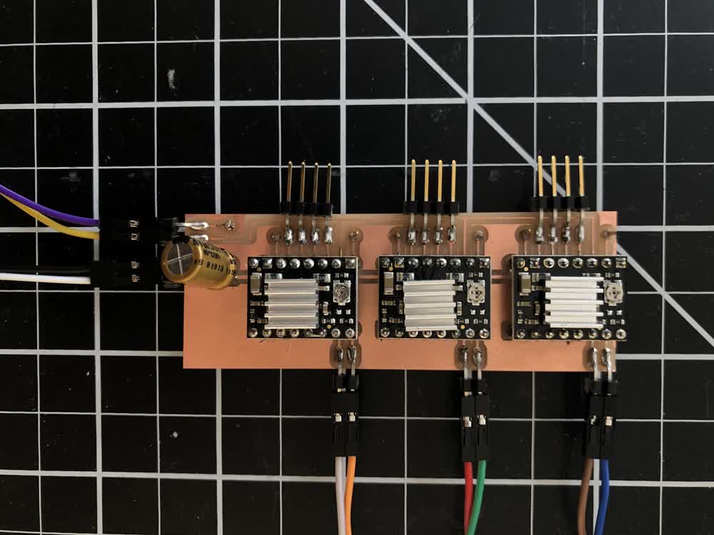 Stepper driver board.
Software
Basket Buddy 2.0 runs of code written in the Arduino IDE using the Adafruit Trinket M0 core. The arduino sketch is attached at the end of the page. I wrote this without the use of libraries, though going forward, adding acceleration and
deacceleration to the motor movements
with the AccelStepper library would be nice.
The Basket Buddy 2.9 interface was written in OpenFrameworks. The basket shown in the video was programmed in OpenFrameworks based on sine and cosine functions.
Final Questions
What does it do?
This is a machine for measuring, marking and cutting lengths of rattan, which can then used to make baskets. Rattan is a natural material made of climbing palms.
Who's done what beforehand?
I haven't seen a machine with this functionality before but there has been some previous work that applies computation and digital fabrication to basket making. Most notably for me is the collaboration between Aranda/Lasch and Terrol Dew
Johnson, titled Baskets.
Some of my early ideating was also inspired by the D.I.Wire in terms of the overall design and in thinking about a machine that transforms a linear material into something that can be
assembled into a larger construction.
What did you design?
I designed the housing and mechanisms. The design of the feed mechanism is based off of the filament feed on a 3D printer. The design and components for
modules two and three was based off of the z-axis of Clank.
I designed the two circuit boards used in the project though the schematic for the microcontroller board is heavily based off of one from Jake found here.
I designed and programmed the interface shown in the video in OpenFrameworks.
What materials and components were used?
Where did they come from?
How much did they cost?
A bill of materials for basket buddy 2.0 can be found here. Some of these parts I purchased, others were from the fablab
inventory. Something significant that is not included are the 3D prints which were done on the ABS printer in the
architecture shop. Depending on access to 3D printing services, this could add considerable cost.
Also, I used the clank PSU to supply 24V to power the stepper motors. This is not included in the BOM but you can find info about that here.
What parts and systems were made?
What processes were used?
I milled and stuffed the circuit boards at home using Clank with the exception of the stepper drivers. During output week I did get a stepper stepping using my version of Neil's bipolar stepper driver but mine was a little inconsistent and I wanted this machine to be as reliable as possible.
The fixtures for the motors and other mechanical components were all 3D printed on the ABS printer in the architecture shop. The plywood housing was milled on the Onsrud in N51. I used the vinyl cutter in the architecture shop to make the
decal.
The embedded programming was done using the Arduino IDE and the interface was made using OpenFrameworks. The communication between OpenFrameworks and Arduino happens over serial. Probably the biggest challenge in terms of programming was
communicating an array of floats over serial and parsing on the other end.
What questions were answered?
I didn't have very much time to prototype the various modules. Everything was just in the computer for the most part until I fabricated everything at the end. So, the biggest question that was answered was, will this machine actually work?
Other questions: Can I hack a pair of reed cutters to be driven by a stepper motor? Can the Clank PSU be repurposed for other projects?
What worked? What didn't?
I achieved the baseline functionality I was interested in but I think everything could work better. Probably the most important improvements would be to the mechanical design and the materials I used. When the machine is running, you can
hear that there is a bit of give in the connections, i.e. there is vibrating if not full blown rattling in some cases. This is especially true of the marking mechanism. I will probably take the machine apart and reassemble to try to make
things stiffer.
I used plywood for the housing because it is relatively dimensionally stable and it is readily available in the shop. To make concealed connections to the plywood I used threaded inserts. These were a real pain to get installed normal to the surface of the plywood creating some misalignment in the
machine. If I were to make the housing again, I would probably use HDPE or something similar and I would probably be less precious about hiding the hardware in favor of accuracy and rigidity.
Also, for the most part the ABS prints are strong enough for what I need them to do with the exception of the spring loaded arm on the feed mechanism. It's starting to deflect under the force of the spring. It is a (relatively) simple part
and it would be nice to machine it from aluminum at some point.
How was it evaluated?
The initial evaluation was simply, can this machine measure, mark and cut rattan with reasonable accuracy? Now the question becomes, how does the machine perform over time? Can it be made to be more accurate? Can it do all of its functions
better than it does at the outside? This will be a matter of tweaking some of the settings in code and adjusting the mechanisms. Specifically, the markiing mechanism could use some work to make a more consistently legible mark. Also, all
the motor movements could be about 100% faster.
What are the implications?
For me, this project is a first step towards making custom machines for making. Rather than just relying on the machines and fabrication processes that are available on the market, being able to design and build my own ways of making feels
very liberating.