Final Project Development
basket buddy 2.0
Over the summer I made a very simple machine for measuring lengths of rattan to be used to make a basket. The idea was that I could model a basket in Rhino as a network of curves, divide those curves based on their intersections with other
curves in the network and feed the lengths into an arduino sketch to drive a motor with gears attached to pull the rattan along. Overall, the machine more or less worked but was very rudimentary.
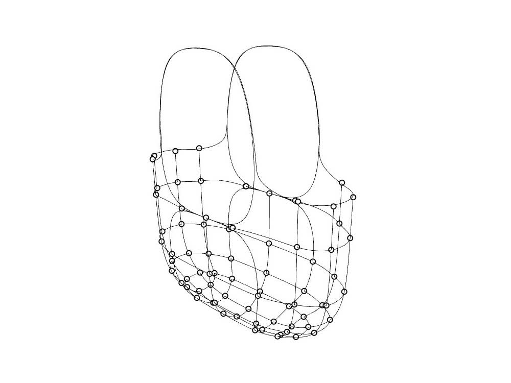 View of Rhino model showing curves and intersections
Video of rattan measuring machine in action.
Images of fully assembled basket.
View of Rhino model showing curves and intersections
Video of rattan measuring machine in action.
Images of fully assembled basket.
In general, and with this project, I'm interested in combining digital fabrication and analog ways of making. Most digital fabrication projects are about designing something on the computer and trying to recreate that with the highest
fidelity possible. I like that this process creates a somewhat messier translation from digital to physical. In addition to the particularities of the hand work, the material used, rattan, is a natural material that has bending properties
that I have not yet integrated into the digital model making the output somewhat unpredictable.
Concept Sketching
My initial proposal for the final project is the second iteration of this machine. Rather than simply measure lengths, my goal is for this machine to also mark and cut the rattan. The machine can be understood as three modules:
- Measuring: Rattan feed mechanism.
- Marking: Device for moving a pencil across the surface of the rattan.
- Cutting: Device for cutting the rattan to length.
My plan is to tackle the modules in that order. Ideally I would at least be able to complete the first two modules, which are the most important, this semester. Before I tackle the cutting mechanism, I might actually devote time towards
developing a GUI for the machine.
The initial design, which I sketched out below includes three motors: one to
drive the feed mechanism; one to drive a linear rail that holds a pencil for marking the rattan; and one to drive a linear rail with a blade attached as a sort of guillotine to cut the rattan.
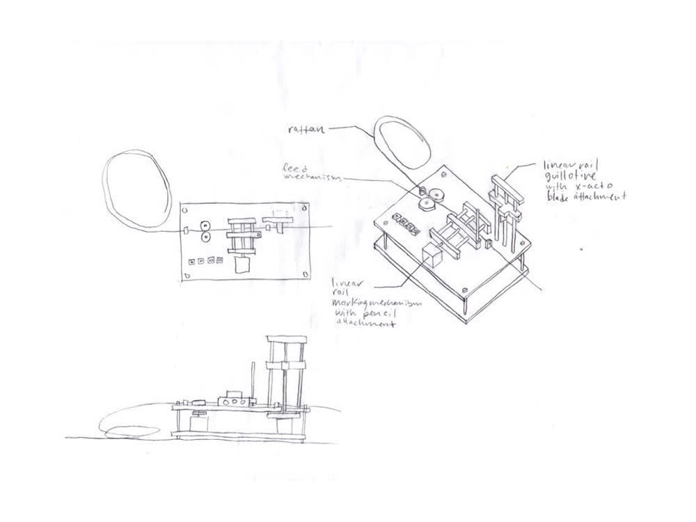 Sketch of proposed updated rattan measuring and cutting machine.
The linear rails seem to be a bit overkill in this context and upon doing further research, I would like to incorporate a device like the "Ordinary Crank Shaft" from 507 Mechanical Movements.
More on that below.
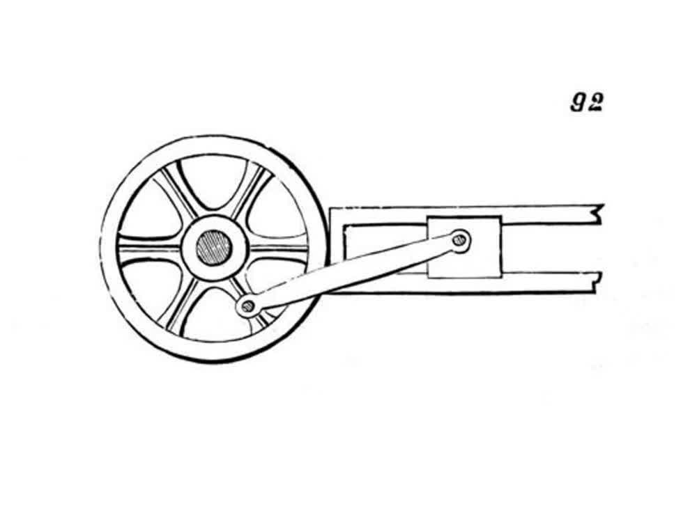 Illustration of ordinary crank shaft.
Sketching out CAD
I am proficient in Rhino and Grasshopper so I decided to try out Fusion 360. Fusion 360 feels very much geared towards manufacturing, whereas Rhino feels a bit more free in terms of the manipulation of objects in 3D space. I could see a
scenario where Rhino could be helpful for quickly sketching out ideas, which could then be brought to Fusion 360 for organization, collaboration and maybe a more streamlined CAD/CAM pipeline. Granted, I have several years of experience in
Rhino, so the clunkiness of Fusion 360 that I experience now would likely go away eventually.
After attending the recitation and watching a few tutorials, I set out to model my initial sketch of the final project. I really like that you can have different part files and that if you update one it propogates through the rest of your
files. That said, I didn't have very much use for that here.
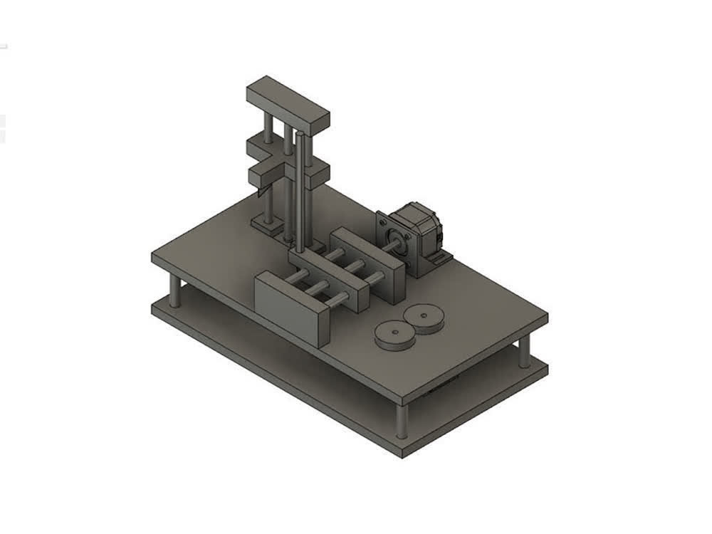 Fusion 360 model axon view of rattan measuring and cutting machine.
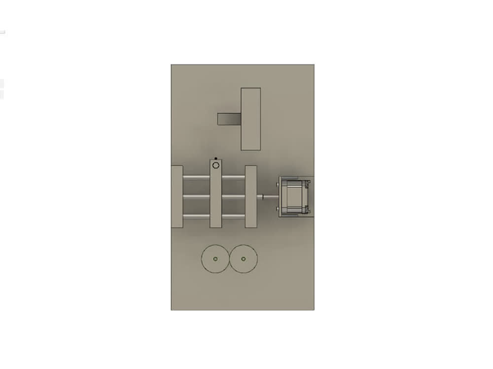 Fusion 360 model plan view of rattan measuring and cutting machine.
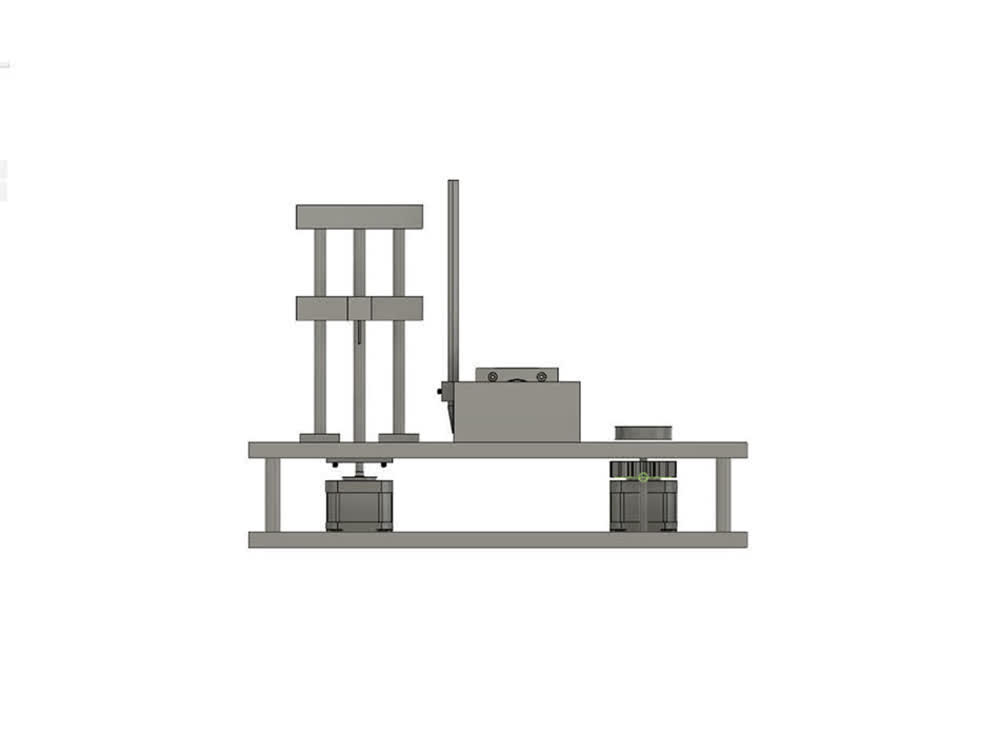 Fusion 360 model front view of rattan measuring and cutting machine.
I'm interested in Fusion 360's ability to create joints and simulate movement between parts. I followed this tutorial by Jonathan Odom that goes over modeling a linear
motion device for 3D printing. This is based on the illustration of the ordinary crank shaft above. The movement is sort of mesmirizing and I would like to incorporate this into my machine. A pencil and small saw could easily be attached to
two of these devices to replace the linear rails in the eariler iteration.
Fusion 360 model showing linear movement.
Updates 200930
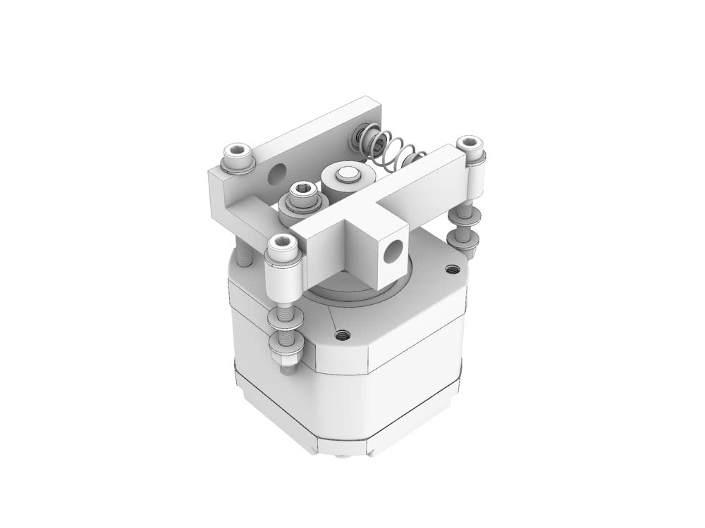
This week I modeled a prototype of the first module. The design is based on a the filament feed mechanism on many 3D printers but is adapted to accept a wider range of rattan sizes. The parts were printed on the ABS printer in the
architecture shops and the hardware has been ordered. I think the holes in the 3D prints may need to be drilled out. I might like to try to mill these parts out of aluminum if I have time..
The basic idea is you have a drive gear mounted to the motor shaft of a NEMA 17 motor and a v-groove ball bearing on arm that is spring loaded. The drive gear advances the rattan while the bearing applies pressure to make sure there is no
slipping.
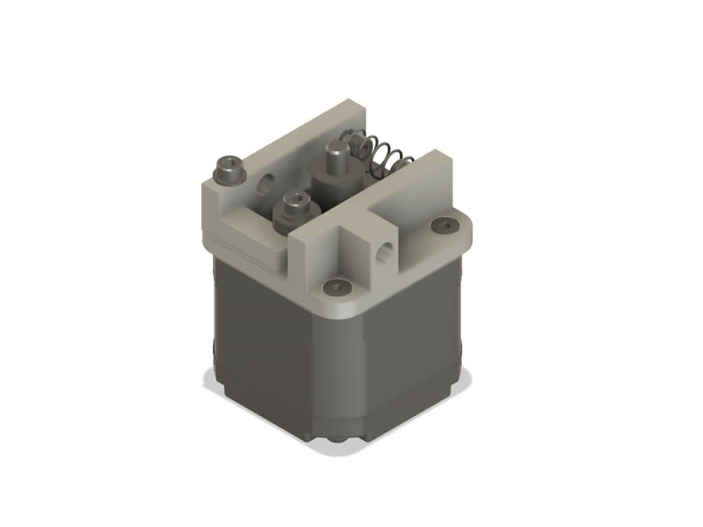 Model of module 01 prototype
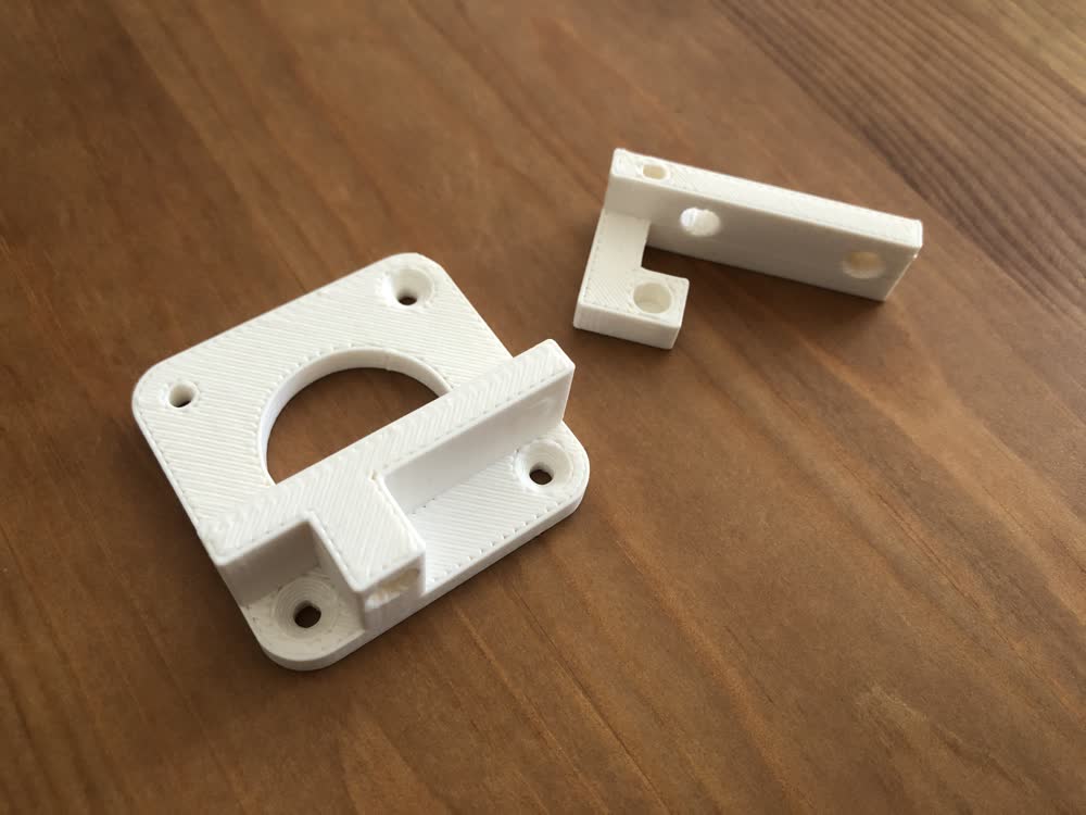 3D printed parts.
Updates 201005
This week I got hardware for the rattan feed mechanism. I experimented with heat set threaded inserts, which took a little bit of practice. Basically, my soldering iron was too hot at first and I ended up with a bit
of a goopy mess. Got the hang of it at the end.
 Heat set insert fail.
 Heat set insert win.
Once assembled, I hooked the rattan feed mechanism up to the motor I had from the prototype and ran the existing arduino sketch. It works well! The movement is much more controlled (and quieter) than the original machine. I'll still make
some tweaks to this part of the design, but the next step is to think about the design of the marking mechanism and how everything gets integrated in terms of the physical layout.
Testing rattan feed mechanism.
Updates 201104
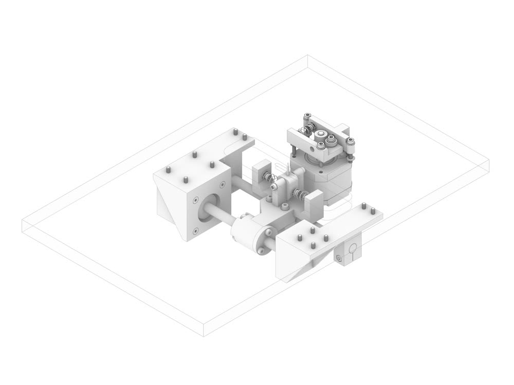
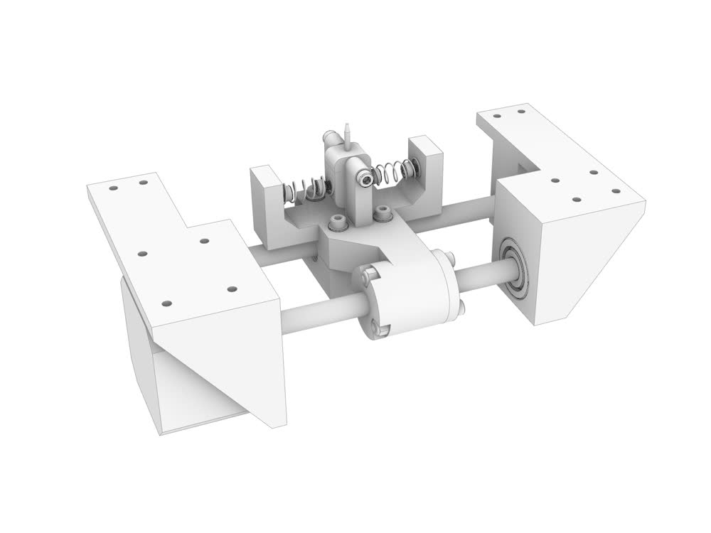
This week I started modeling the final assembly of the machine. So far I have modules one and two fully modeled. The rest of this week and weekend I plan to finish modeling so that I can fabricate next week. Any of the more
complicated parts will simply be 3D printed. The housing will be made on the Onsrud from baltic birch plywood.
 Progress.
 Progress.
This coming week is about output devices, which is an important one because this project is all about driving stepper motors.
Updates 201118
I spent a lot of time on the final the past two weeks, finalizing the design and fabricating. Everytthing that needs to be fabricated or printed is in place and I have all the mechanical parts I will need. Somethings definitely won't
go as planned but I will have to play it by ear considering we're losing shop access this week. Next major focus will be circuit design and then interface.
 Module 1 - feed mechanism.
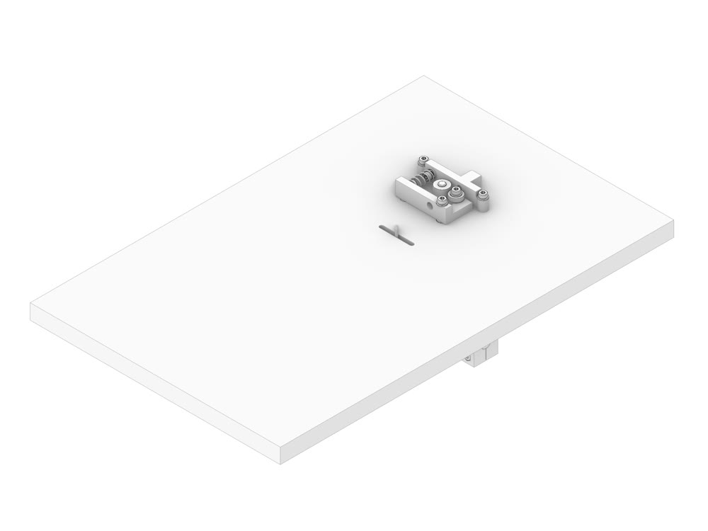
 Module 2 - marking mechanism.
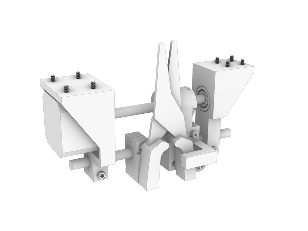 Module 3 - cutting mechanism.
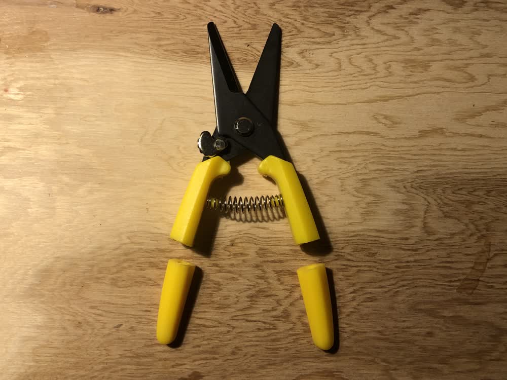 Sawed off reed cutters.
 Module 3 - cutting mechanism in progress.
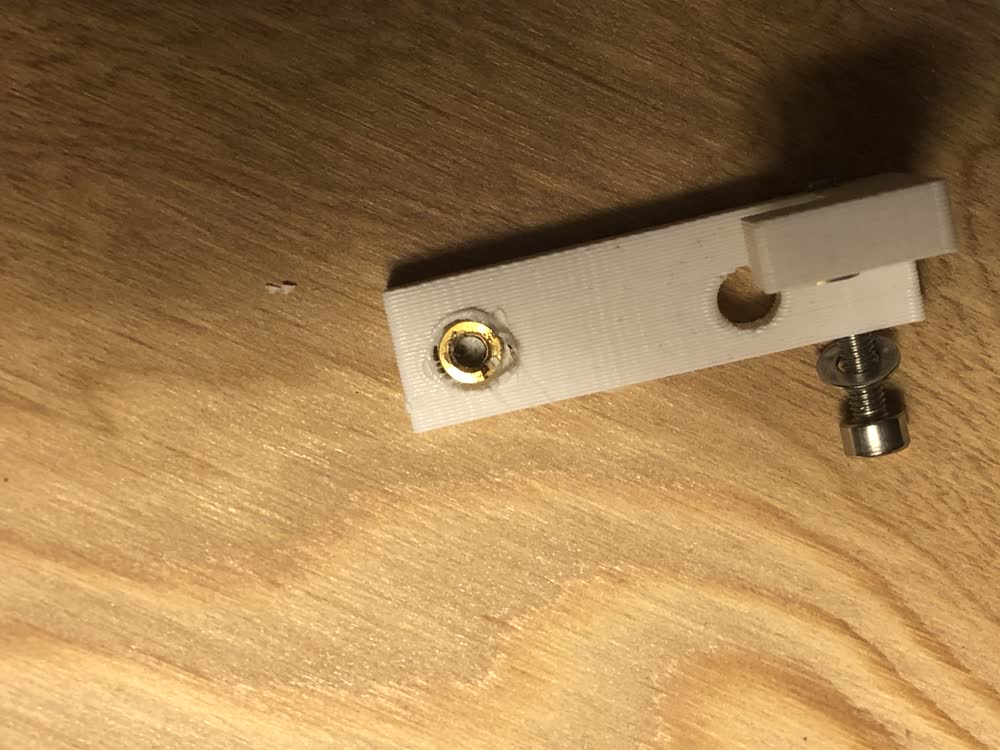
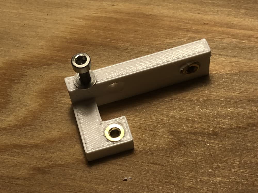
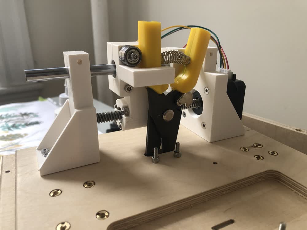
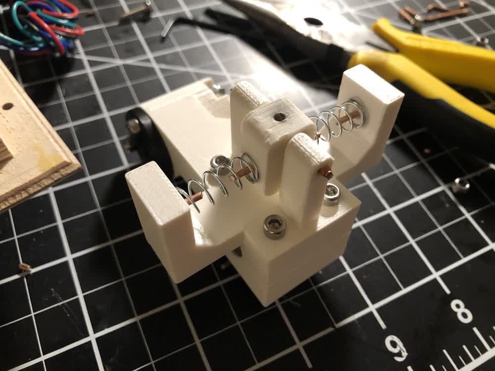 Spring loaded pencil holder.
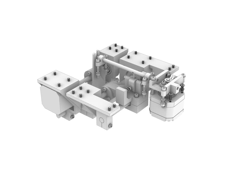 All modules.
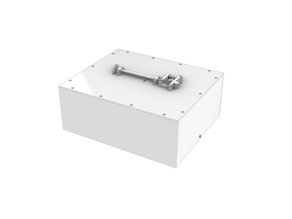 All modules in housing.
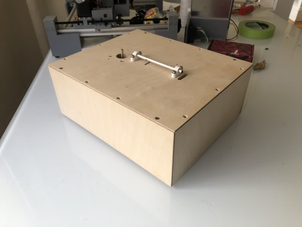 Housing IRL.
Updates 201209
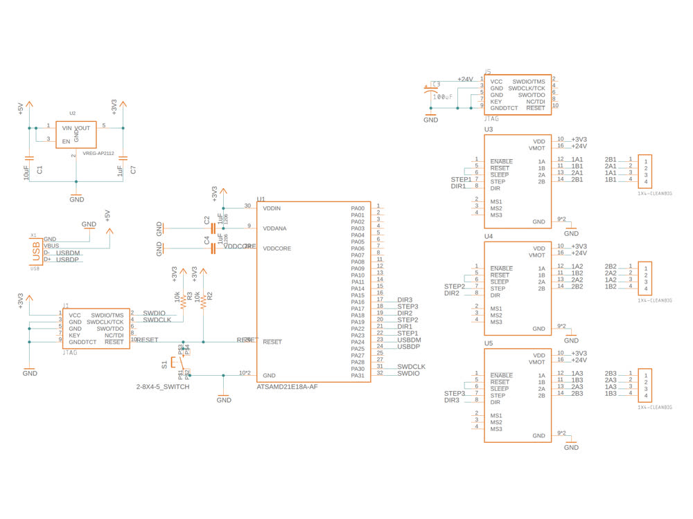
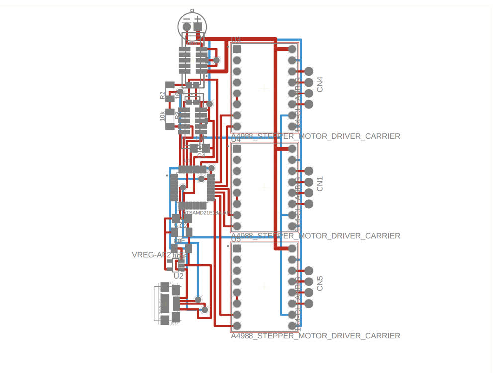
This week I set out to fab a board to control the three motors that make up my final project. Mistakes were made. I made a SAMD21 board based off of Jake's design found here but added 3x Pololu A4988 stepper drivers. The board had a lot of design flaws that I only realized once I had made it. I was able to flash a bootloader to
it and program it from Arduino, but the USB connection was somehow unstable. This might be cause by how I routed the USBDM and USBDP traces with sharp turns and vias, which I have learned is not advisable. I also used a capacitor that
was only rated for 16v on a circuit receving 24V causing it to explode. Lesson learned there. I was also trying to power this board from the clank PSU and included an extra JTAG header because I thought that was how I could connect to
the PSU but I was mistaken.
 Disaster schematic.
 Disaster schematic.
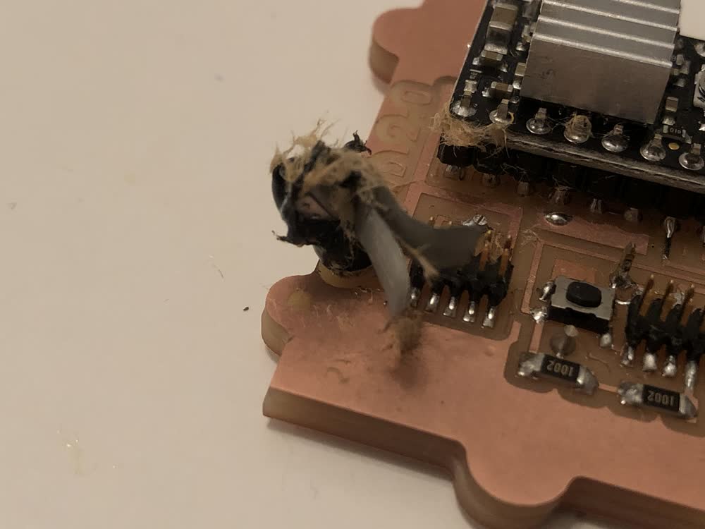 Capacitor disaster.
After a lot of troubleshooting I decided to take a step back and fab a board that just breaks out the pins of the SAMD21 without the drivers. I used the Adafruit Trinket M0 bootloader. One thing to note about this is that though my
design breaks out most of the free pins on the SAMD21, the Adafruit core only has pin mappings for 6 of these pins, because that is all that they make
available on the Trinkets that they sell. You can find the mappings here..It is possible to access the other pins through port manipulation, but I haven't gotten that far yet. Once
the
bootloader was succesfully flashed, I just had to install the Adafruit core in the Adafruit IDE and was up and running.
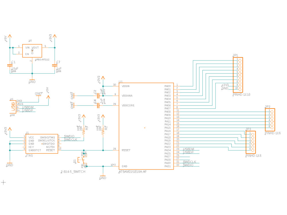 Modified Trinket M0 schematic.
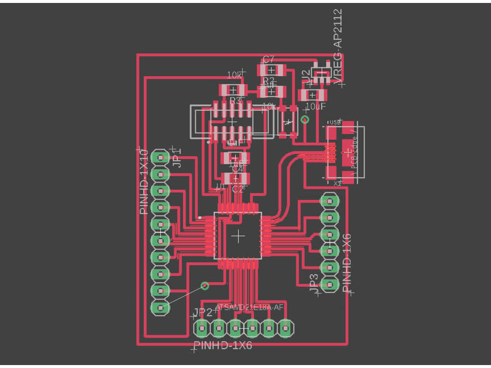 Modified Trinket M0 design.
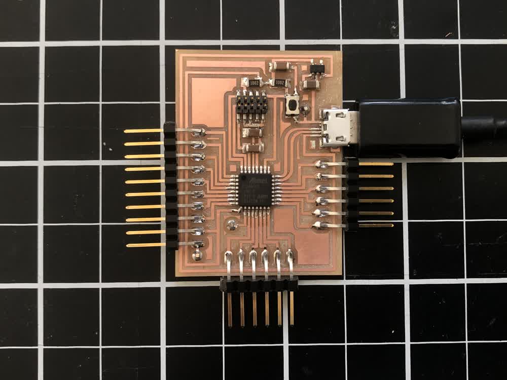 Modified Trinket M0.
Here is some simple code that I'm using to step the stepper.
#define dirPin 0
#define stepPin 1
#define stepsPerRevolution 200

void setup() {
  pinMode(stepPin, OUTPUT);
  pinMode(dirPin, OUTPUT);
}

void loop() {
  digitalWrite(dirPin, HIGH);

  for (int i = 0; i < stepsPerRevolution; i++) {
    digitalWrite(stepPin, HIGH);
    delayMicroseconds(2000);
    digitalWrite(stepPin, LOW);
    delayMicroseconds(2000);
  }

  delay(1000);

}
!!!
This week I also made connection between OpenFrameworks and my board. I'm going to use OpenFrameworks to control the final project so this was an important step and was smooth to get up and running. You can see more about this on
my interfaces and application programming page.
Next steps are to design and fab a board to hold the stepper drivers and finish assembling the mechanisms. Fingers crossed that the mechanical parts actually work because it will be difficult to iterate on that without the shop.