Weekly Progress
Week 2: Electronics Production
PCB Milling and Soldering
This week's task was to mill a copper PCB board and stuff the board with soldered-on electronic componenents.
I have minimal experience with electronics, and have only really used bread-boards in my prior work. Both milling a board and soldering were new techniques to me. As an architect, working at this micro scale is an exciting challenge and interesting persepctive shift.
We were given the schematics for a hello.DC11C.serial.5V.1.1 board and images for the interior cut and outline for milling the PCB board from a copper plate.
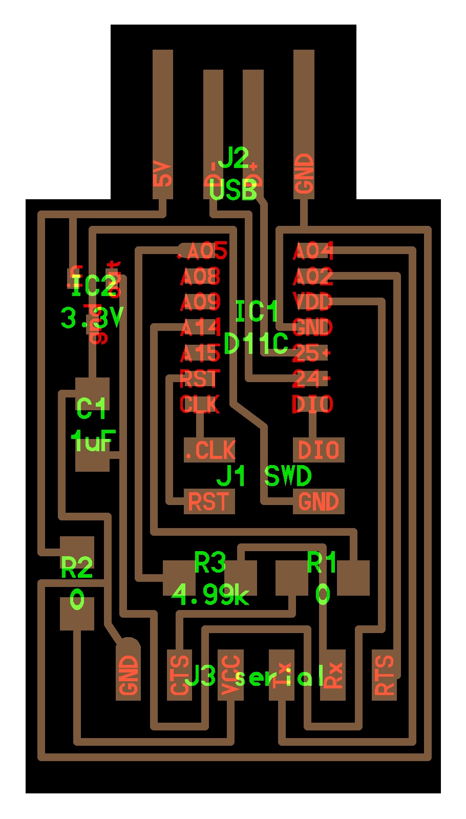
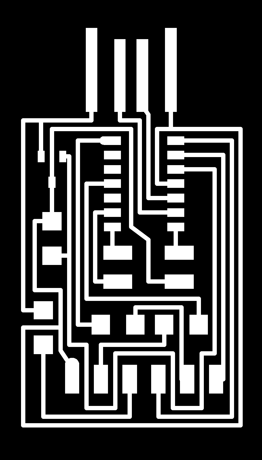
Step 01: Milling
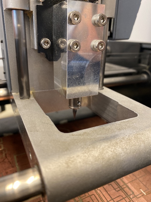
The ArchShops are equiped with two Roland Modela's for PCB milling. One is a slightly newer version than the other, but both pimarily operate the same way. (Minor differences are that the older machine connects to the computer via an older serial connection rather than USB and has a manual control for jogging in the z axis)
When getting started it is essential to make sure that both the milling bed and the piece being milled are completely flat. At this scale where we are millling away fractions of a millimeter, the smallest imperfection can make a big difference. The shop staff maintain the milling bed, but it is important to clean it before and after every use. When choosing a copper plate, be sure to check for bowing. Use double sided tape to attach the plate securely to the bed.
It is important to properly zero the origin of the plate in order to minimize wasted material. Carefully setting the Z-axis will ensure the endmill is in the collet in the correct position. These endmills are particularly fragile (and expensive), so be careful when handling. For milling the interior circuitry, we use a 1/64" endmill. To cut the piece out, we use a 1/32" endmill.
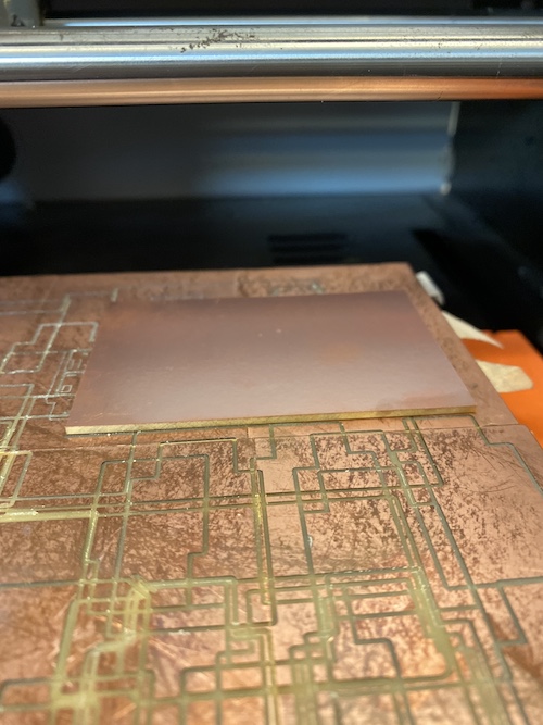
First our group section did a test to see just how thin a 1/64th endmill could cut a copper strip (see below image).
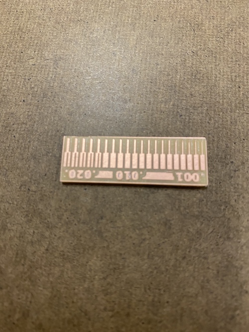
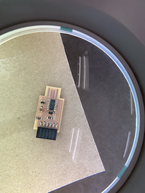
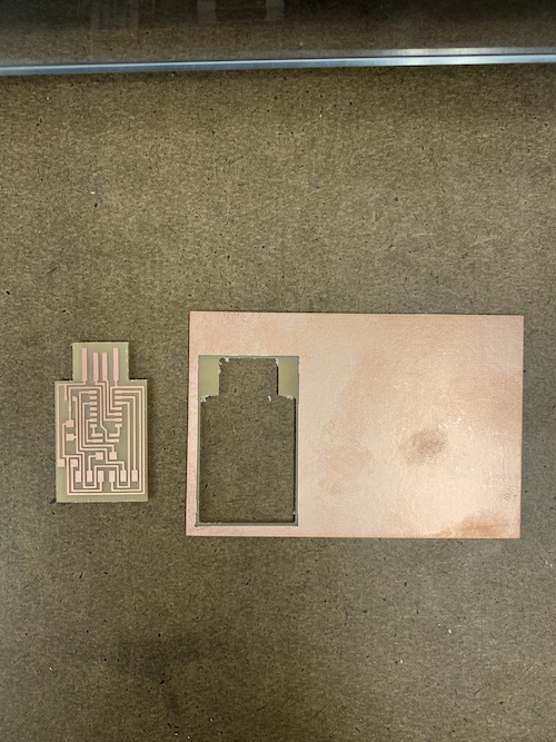
I then milled out my PCB board.
Step 02: Stuffing the Board
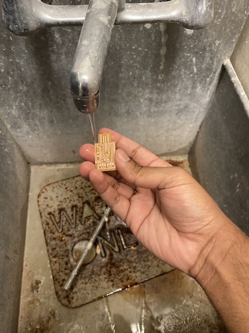
The first step to stuffing the board is to thoroughly clean the PCB board. A small amount of Gojo soap and water will do the job, but it is important to do this immediately before soldering as dirt and oils from your hands will erode the board.
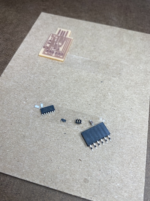
Once at the soldering table, collect all components to be stuffed on the board (see board schematics for details). It is helpful to attach the board and components to a small sheet than can be rotated easily with double-sided tape.
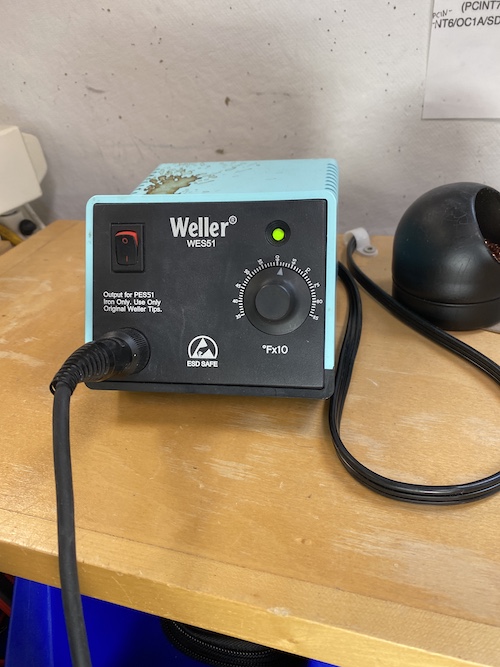
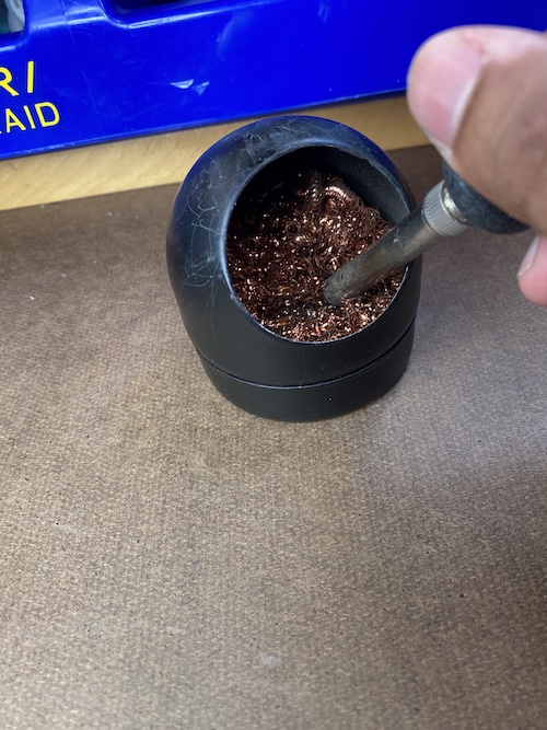
Set the soldering iron to ~600-650 F. And make sure the iron is clean by heating some solder on the tip and cleaning it in the metal sponge.
Soldering requires some practice (and precision with fine motor skills), but becomes easier once you develop the intuition for how to hold parts in place. It is a good idea to work from the inside out to give ourself to most room to work.
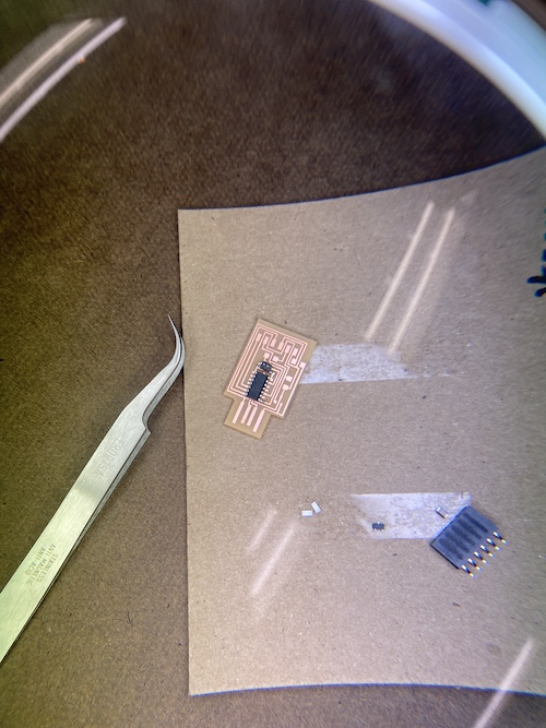
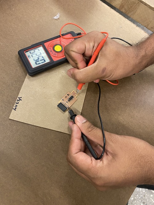
Once the board was completed, I tested it using the multimeter to ensure all connections were working. The appeared to be test was successful as all ends appeared to conduct a charge when connected to the GND.
Step 03: Conclusions
This is a process that will clearly become easier (and faster) with experience. I am quite happy with how my first PCB board turned out -- though to be honest I'm not entirely sure what to do with it! I look forward to understanding how to program a board like this in the coming weeks and to begin designing my own.