Week 10
Tip of the Week
It was incredibly helpful this week to have an Arduino Mini Pro and a Neopixel Flora on hand to help with troubleshooting. It allowed me to run the same test code on in all combinations to quickly identify which component had the issue, if any.
Output Devices - Two-Face Neopixel Flora
Concept
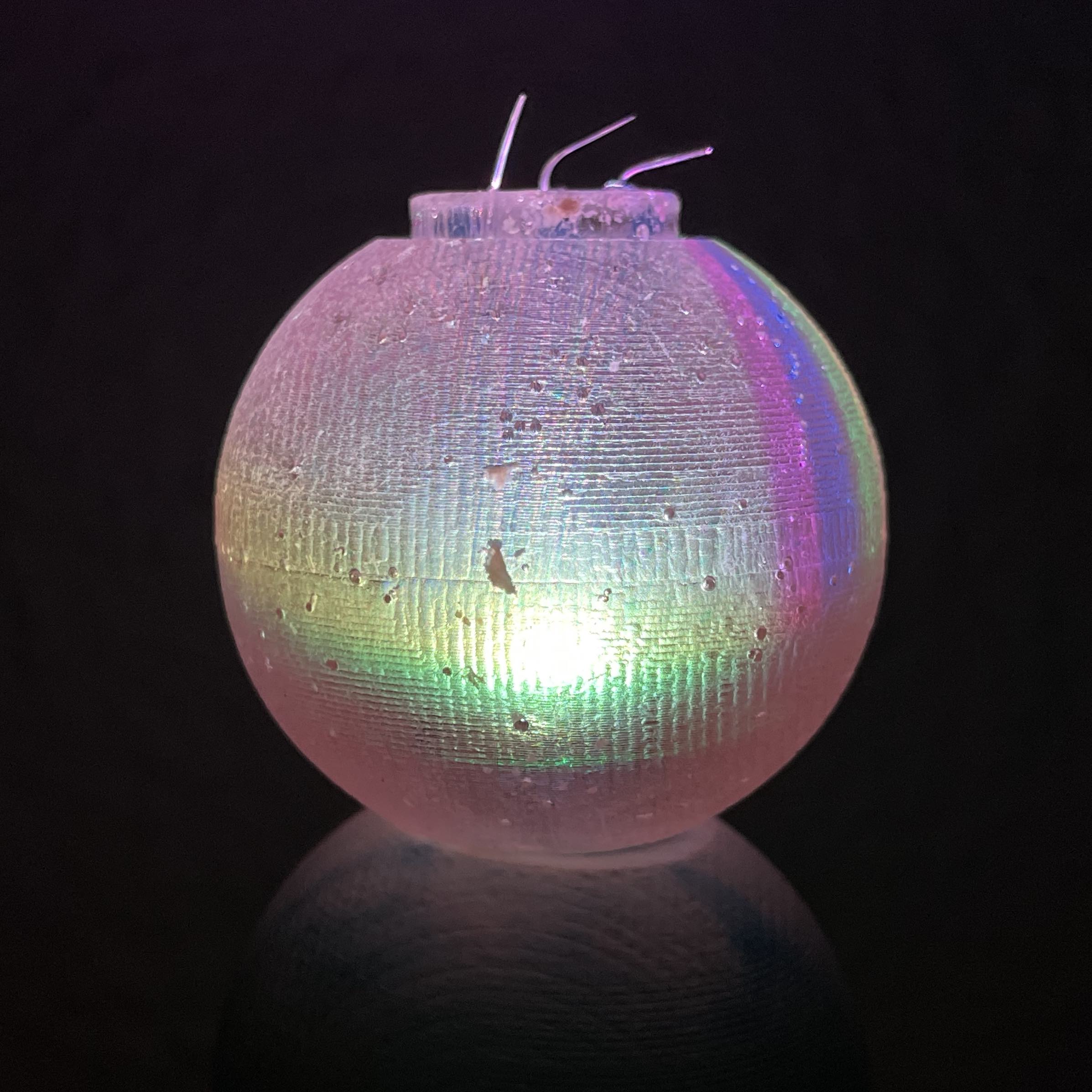
This is a continuation of the past few weeks with an improvement on my Week 8 Molding & Casting project. The goal was to create my own Neopixel Flora boards that had an addressable RGB LED on both sides. The plan is to also have this be controlled by a Capacitive Touch Input Device, but that's been giving me trouble.
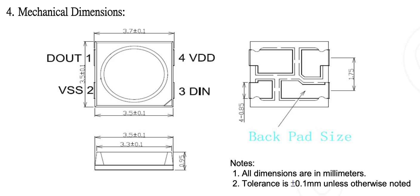
For this project, I used the NeoPixel Mini 3535 RGB LEDs with Integrated Driver Chip
Week 8 Project
Designing the Board
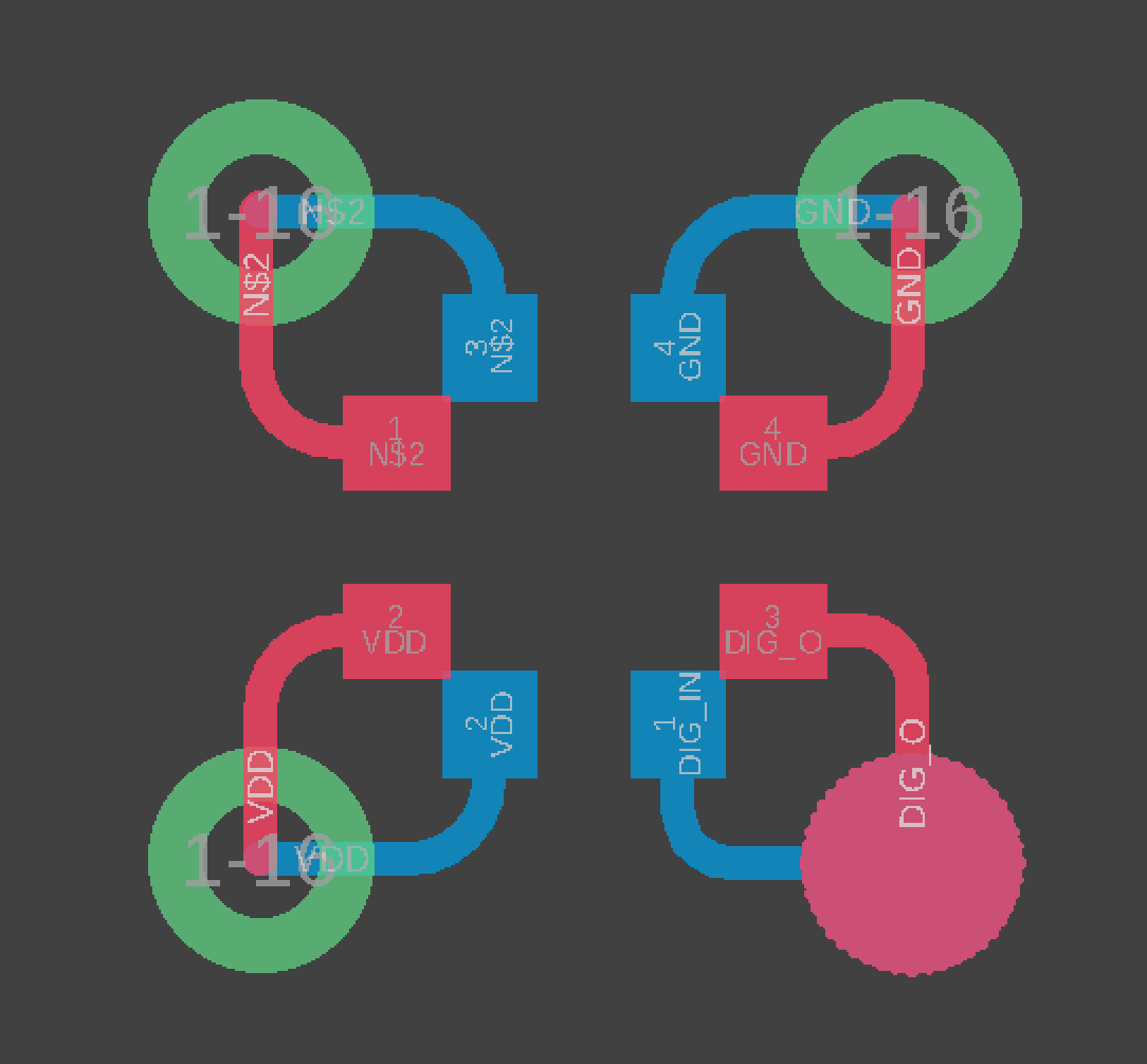
The key to the design of this board was to not get confused about the orientation of the two boards. It is most efficient to line them up so the digital signal comes into one side, passes through the first pixel, then goes through the board to the digital_in of the second pixel, and finally out the second pixel to connect to another board. Both the ground and VCC wires can go straight through a via to connect to both pixels.
I then made some modifications including a hexagonal board shape in Photoshop. Great time to reduce size by 50% if you're on a mac due to an Eagle bug. I also took this time to setup a series of 4 boards to be cut at a single time.
Front Side - Mill these first and don't use the back side!

Outline & Vias - Mill these second, making sure that you change directions in Mods to have them cut the vias first.

Back Side - Mill these last, taking extra care to adhere them to the board in the exact same place they were cut out of (if using Roland). You will need to rotate the board to ensure the corner without the via is in the bottom left.

Soldering
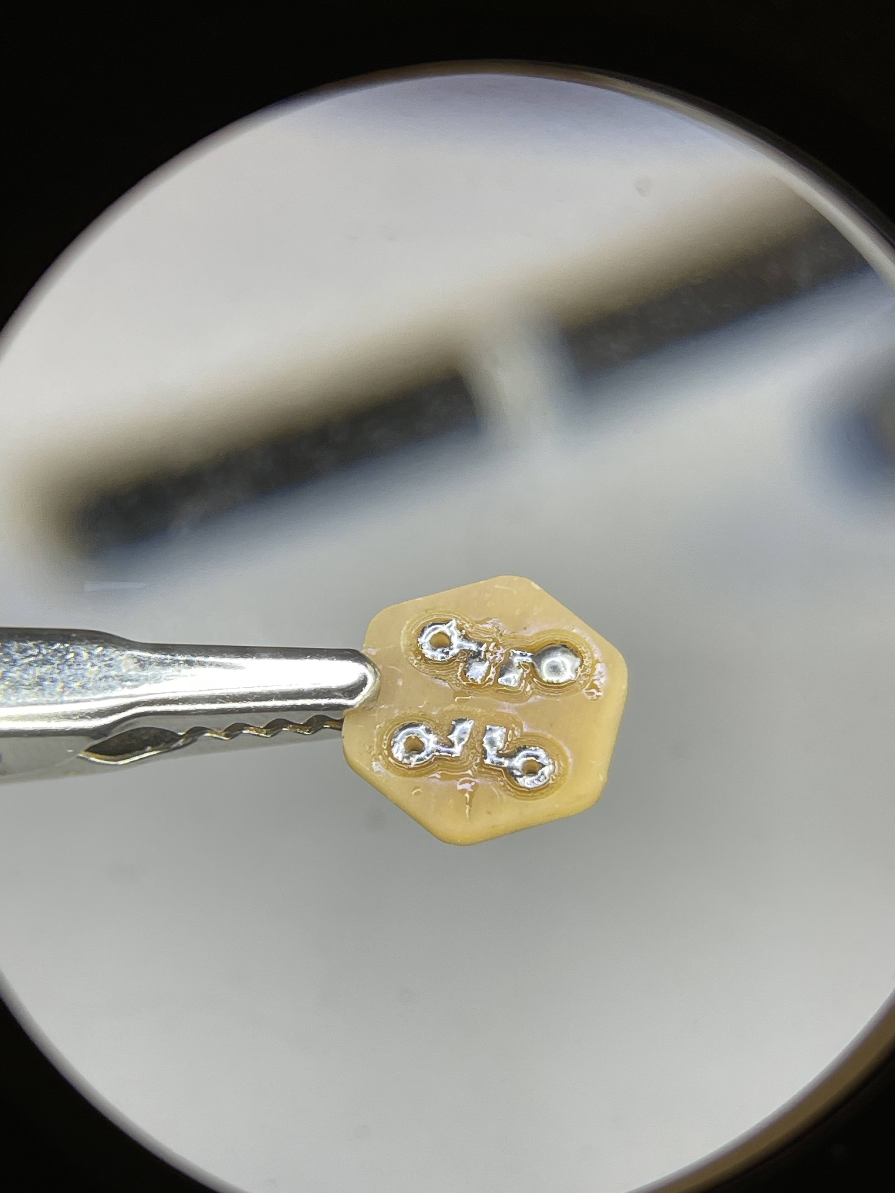
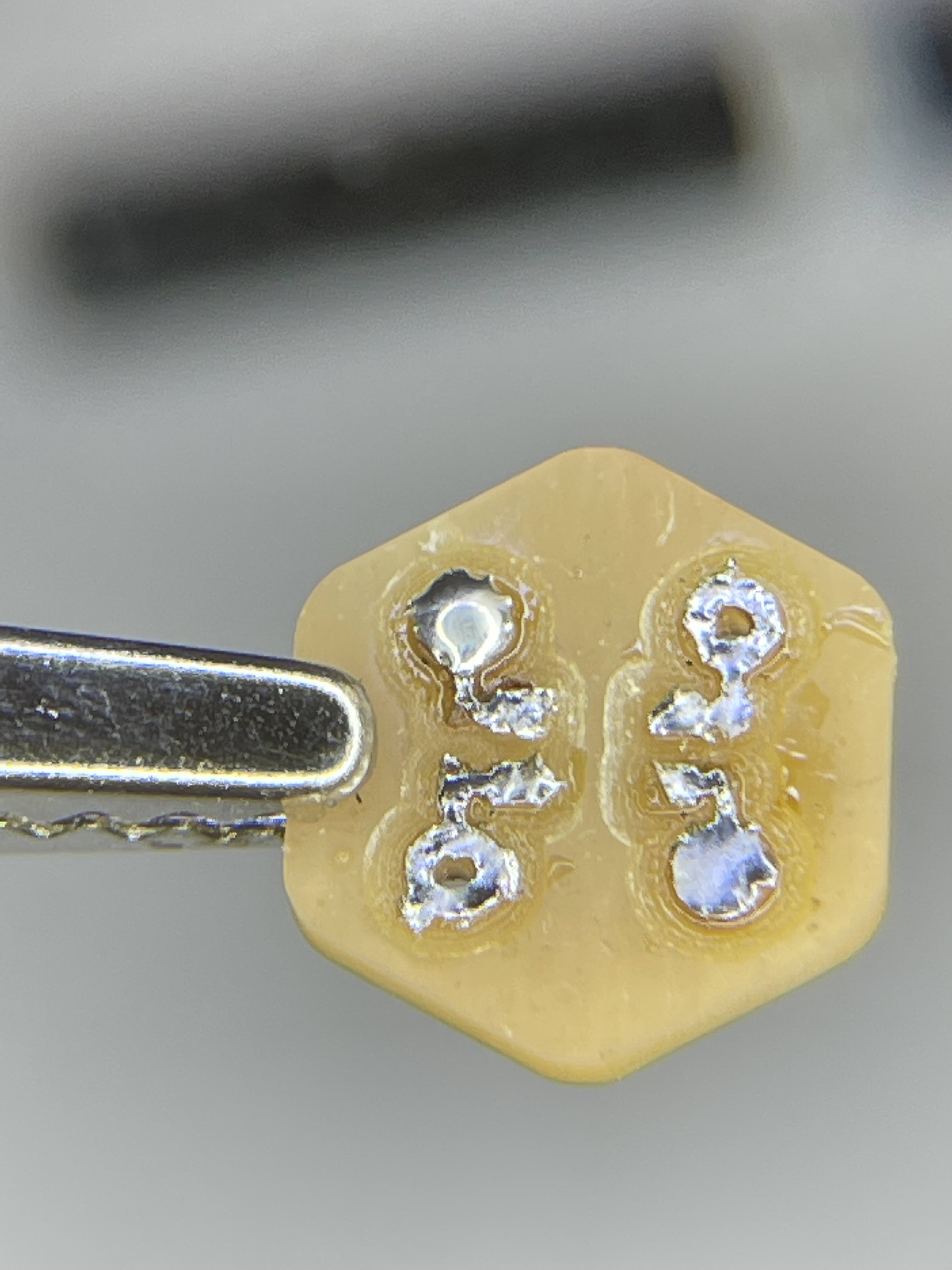
Step 1: Coat the Pads
Start by coating the pads with solder on both sides. Aim for relatively flat and you don't need a ton, except for the corner pads without vias. For those, add a little extra
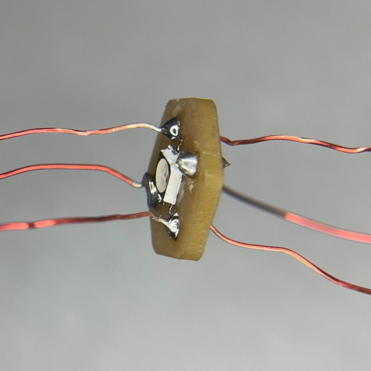
Step 2: Place RGB LED
Doesn't matter which side you select as the front. However, place the corner with the triangle (digital in) at the corner without a via (you will place this on the opposite corner for the back side).
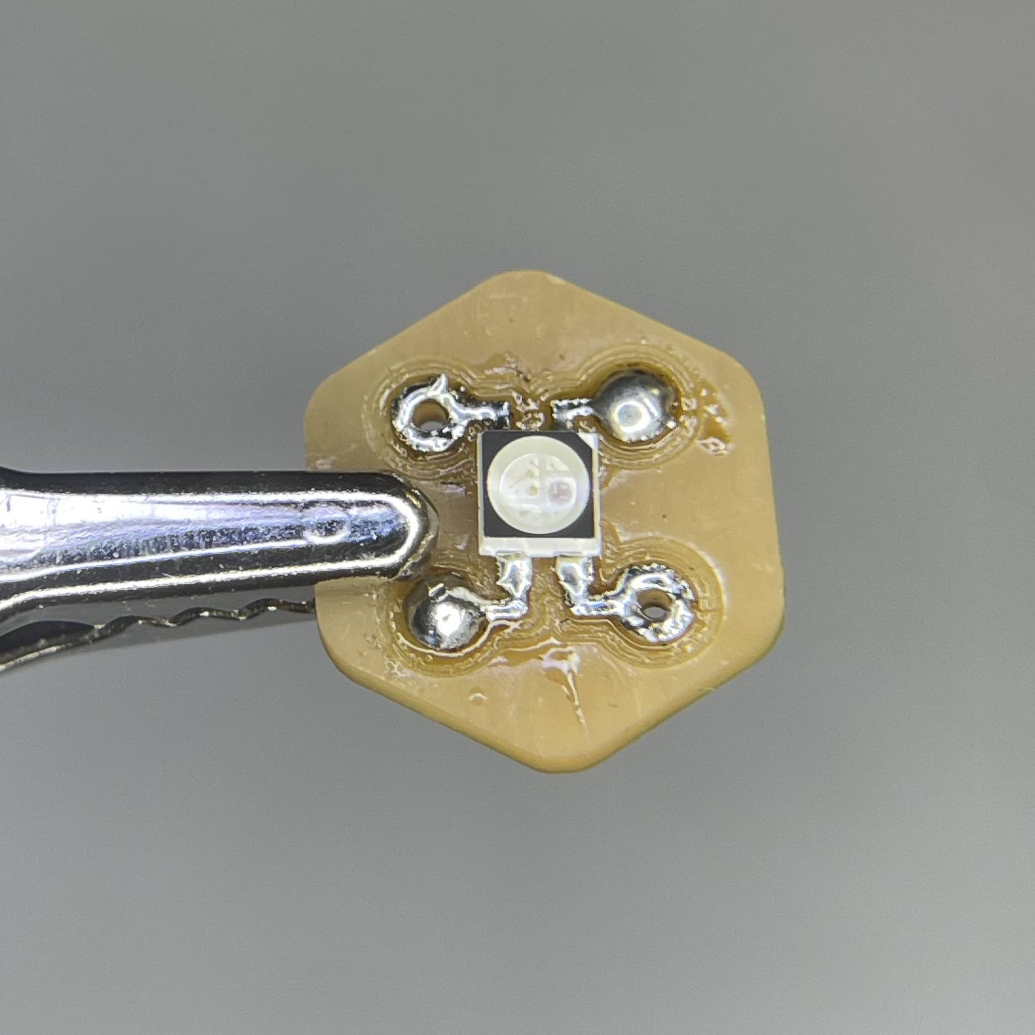
Step 3: Solder RGB LEDs
To do this, gently touch the solder just outside on of the pads, just to create adherence. Then gently squeeze RGB LED to create downwards pressure as you melt the solder at the other pads. Lastly, add a lille more solder to solidify connection. Repeat on both sides, paying attention to alignment.
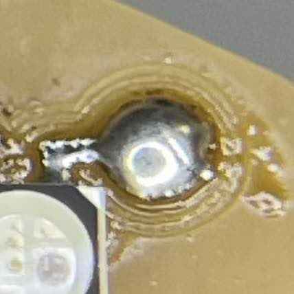
Step 4: Create Via Connection
Strip a solid core wire and slip it through the via, just barely poking through. Then close that off by soldering. Flip the board, clip the wire, and close the solder on the backside.
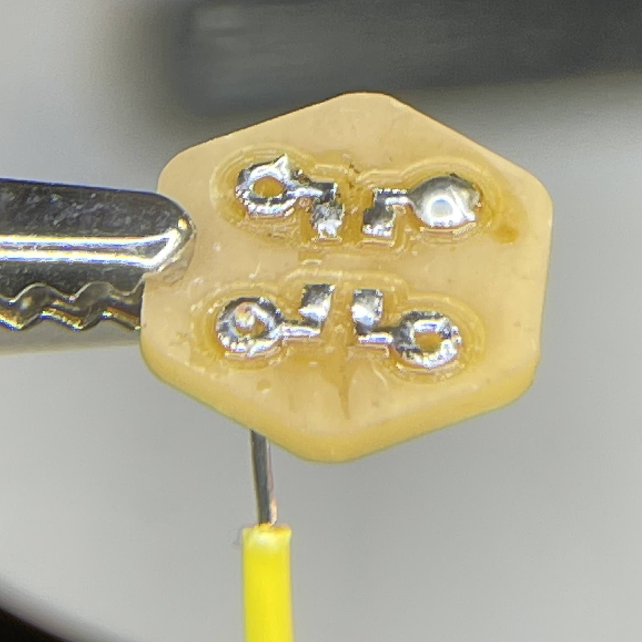
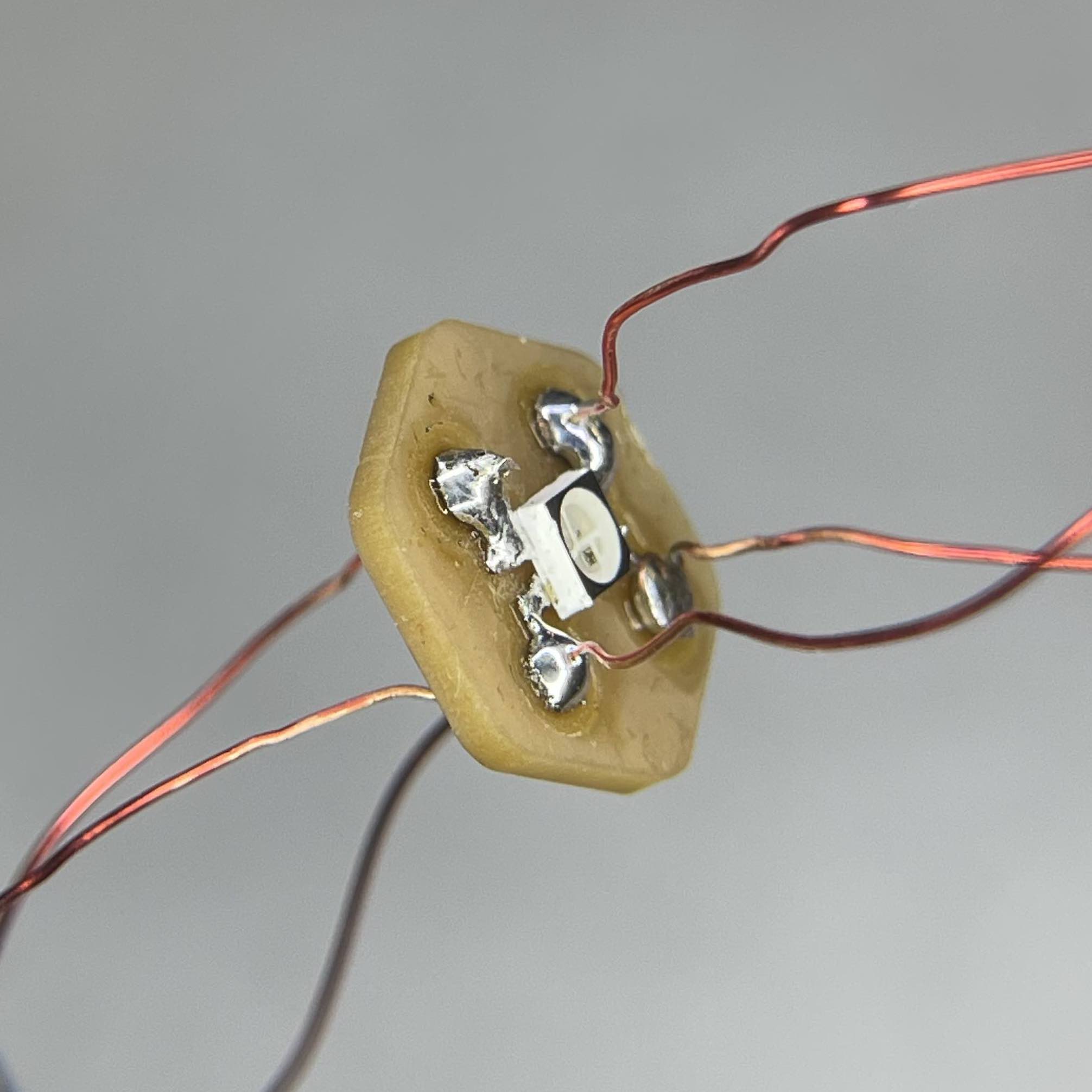
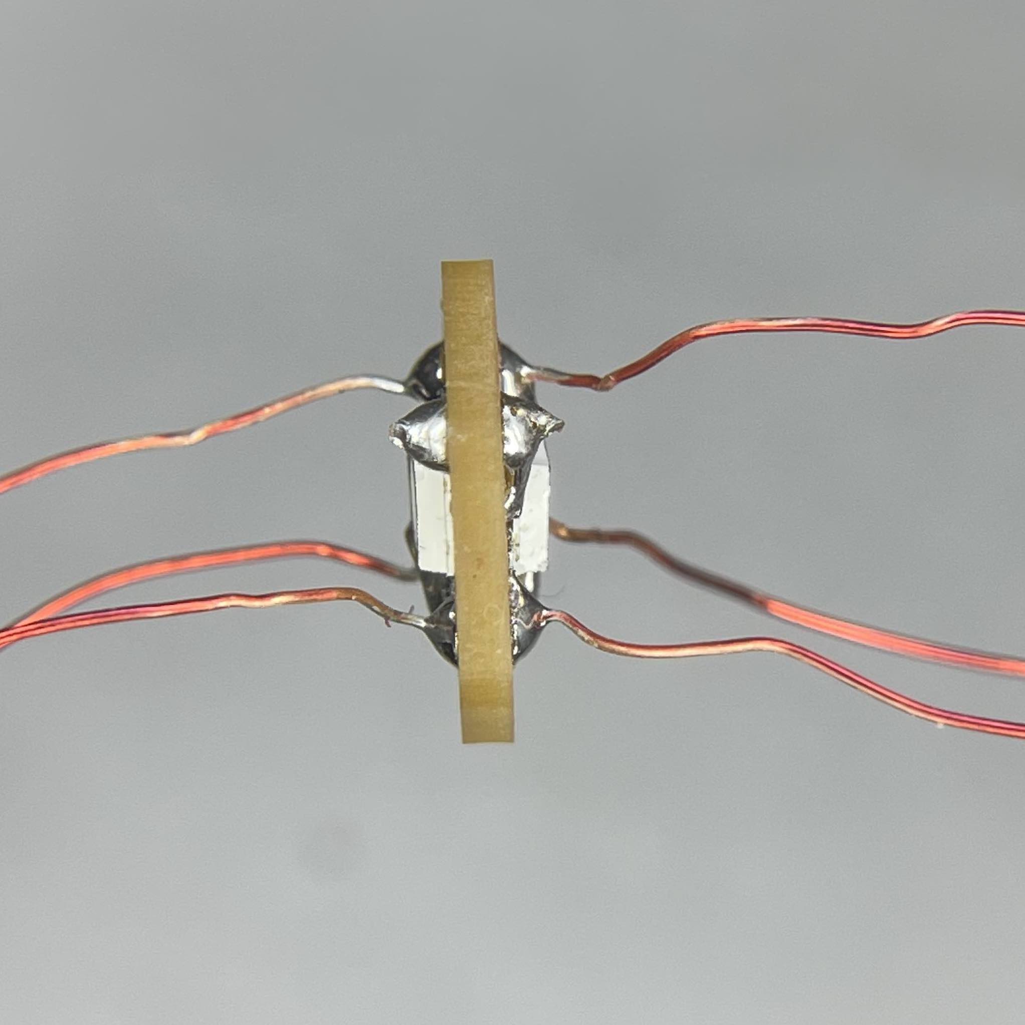
Step 5: Thread and Solder the Ground and VCC
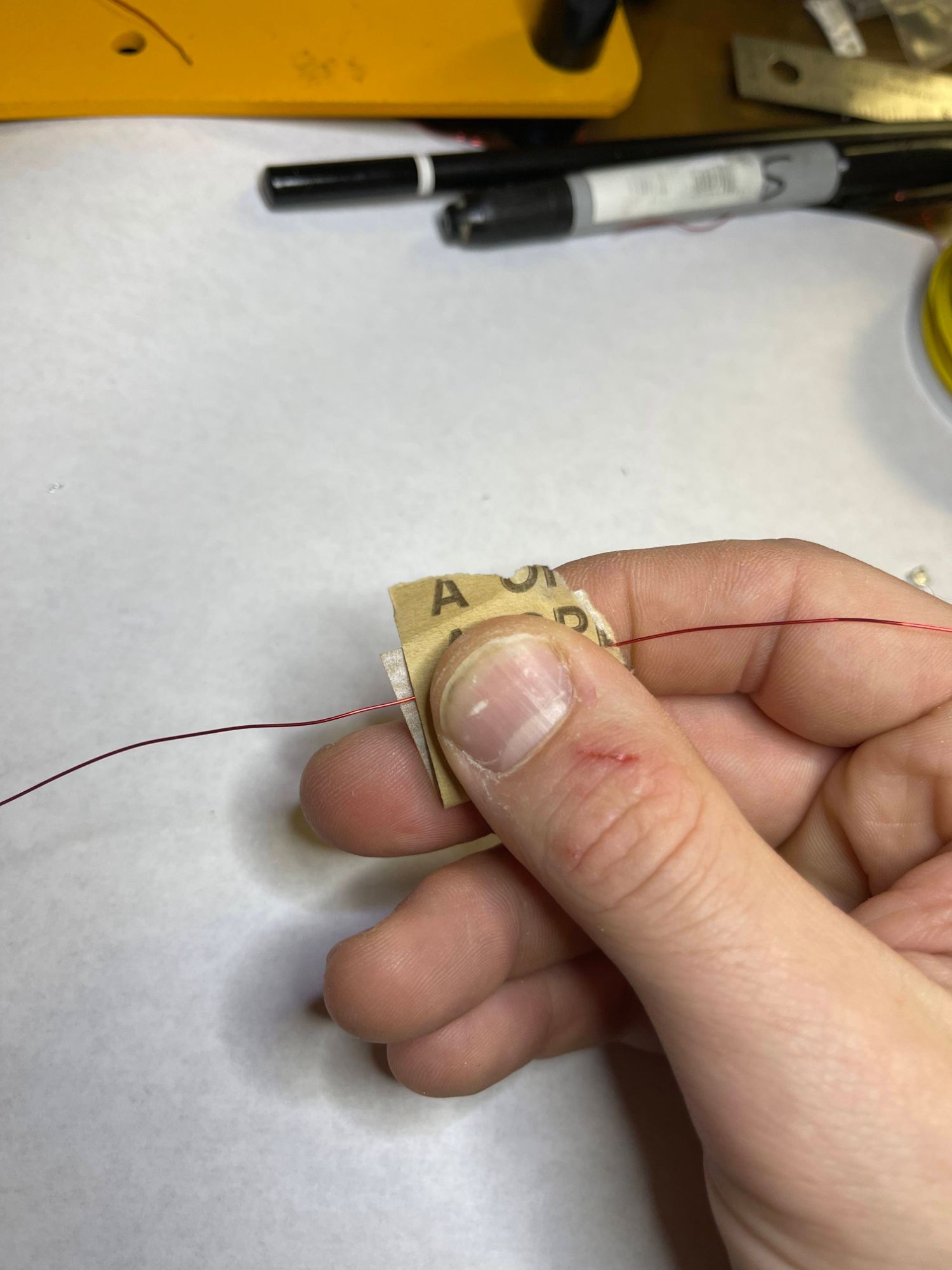
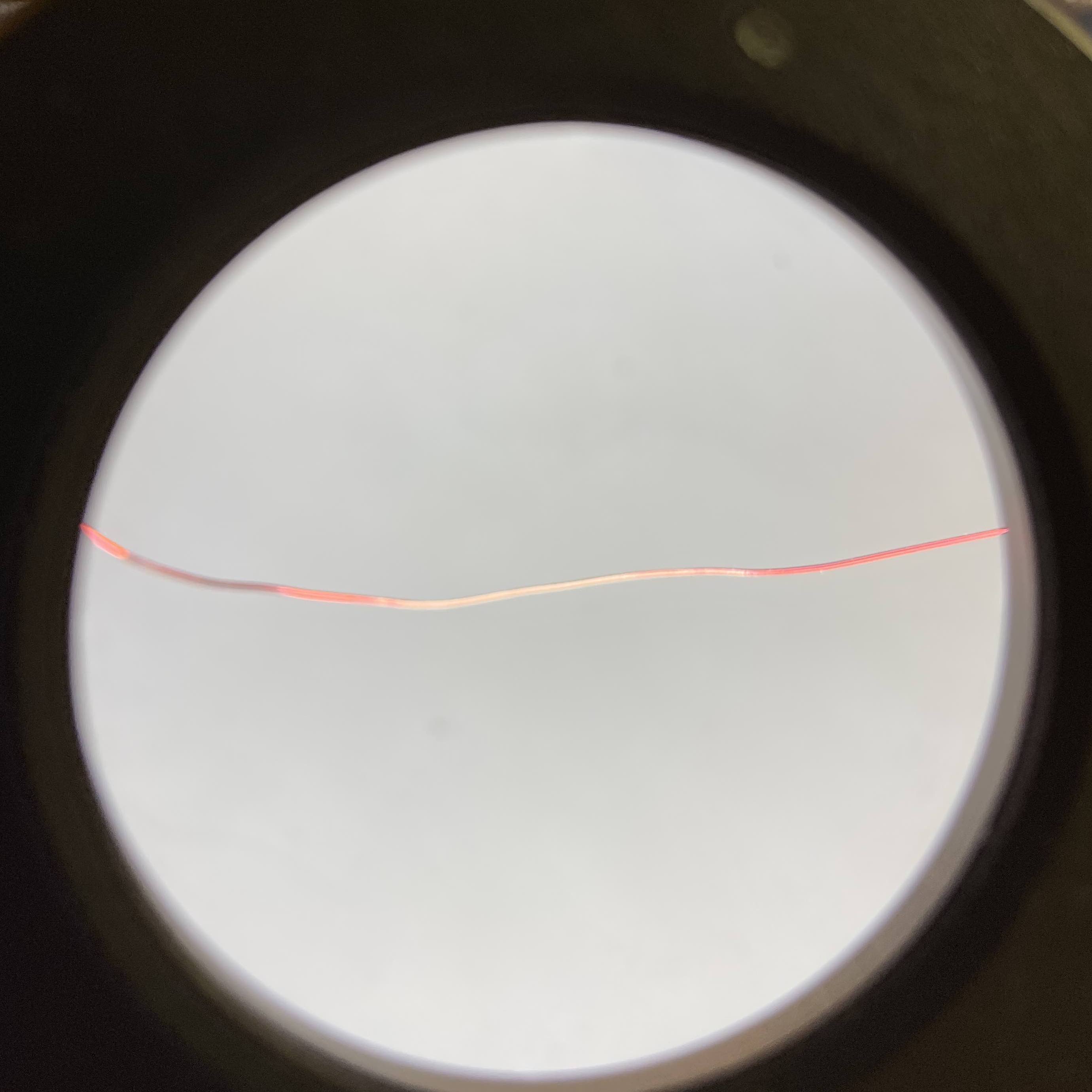
I used magnet wire due to aesthetic reasons, but you could use other options. With the magnet wire, sand about a .5" section of a 7" piece of wire. Use 320 grit sandpaper and not a blade, that will damage the already thin wire. It is sort of hard to see the color difference, but here is an image to help.
Next, thread the wire through a via with just about .25" of copper showing above. Stabilize using helping hands. Solder the top side of that wire, then repeat for the other via. After this, flip the board and solder the backside.
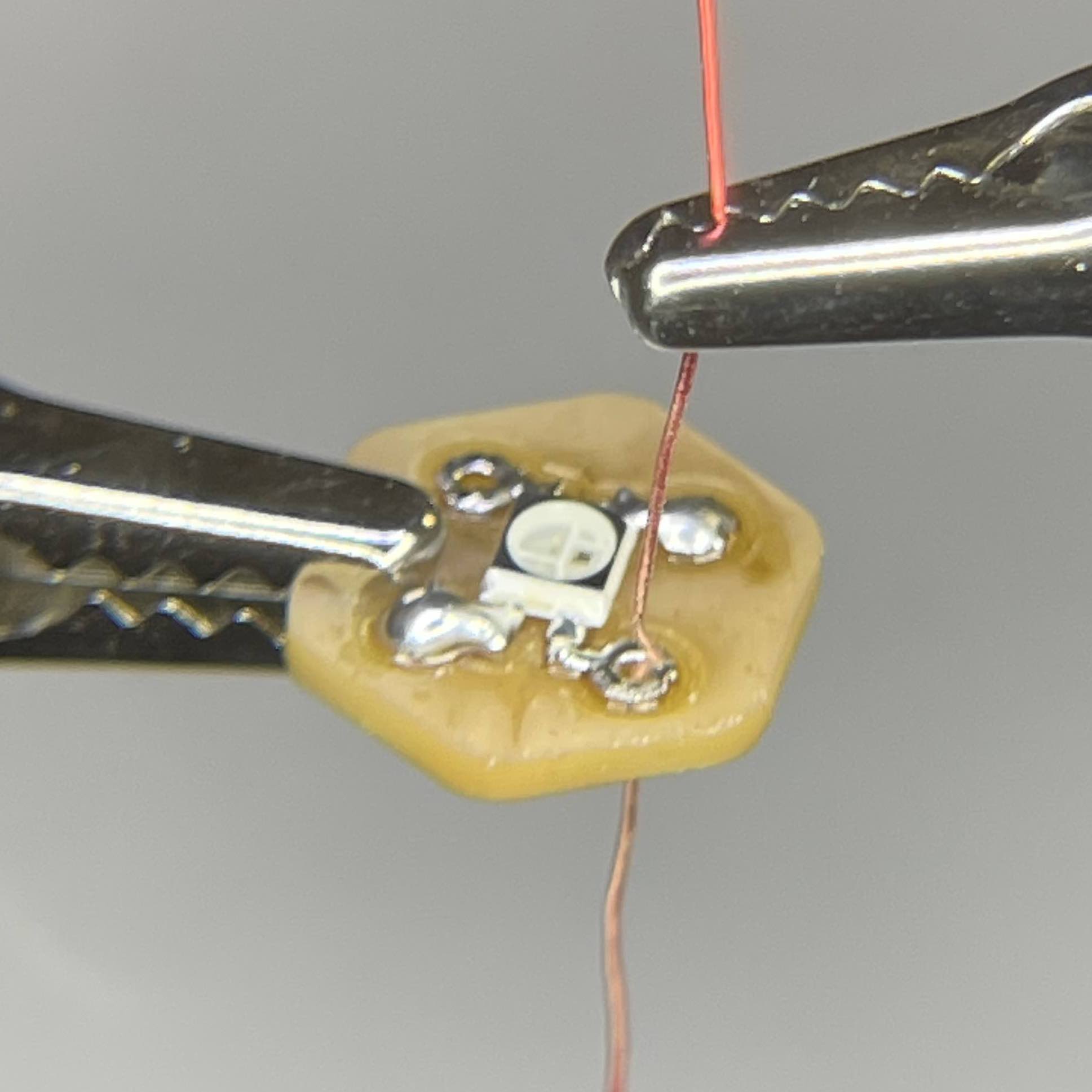
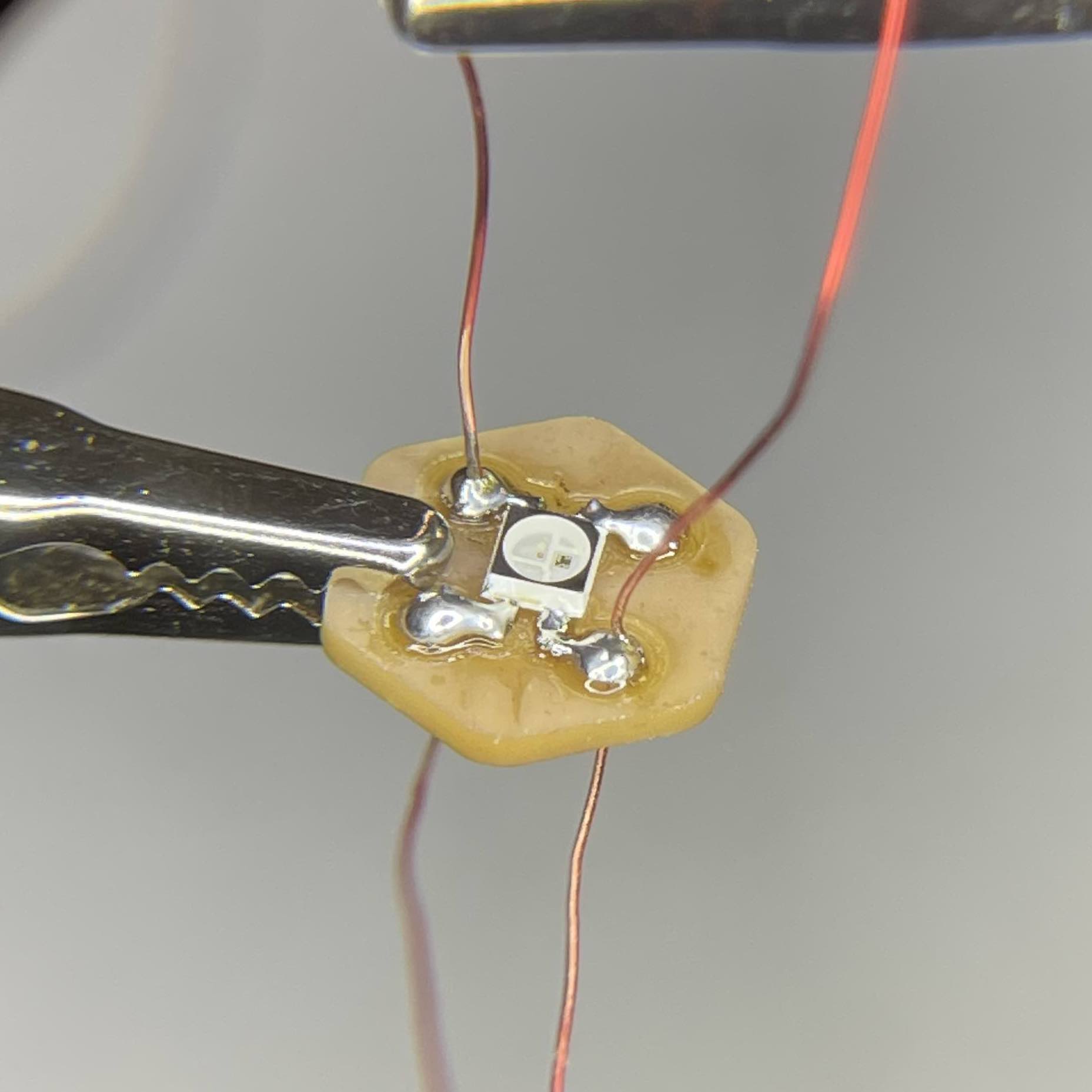
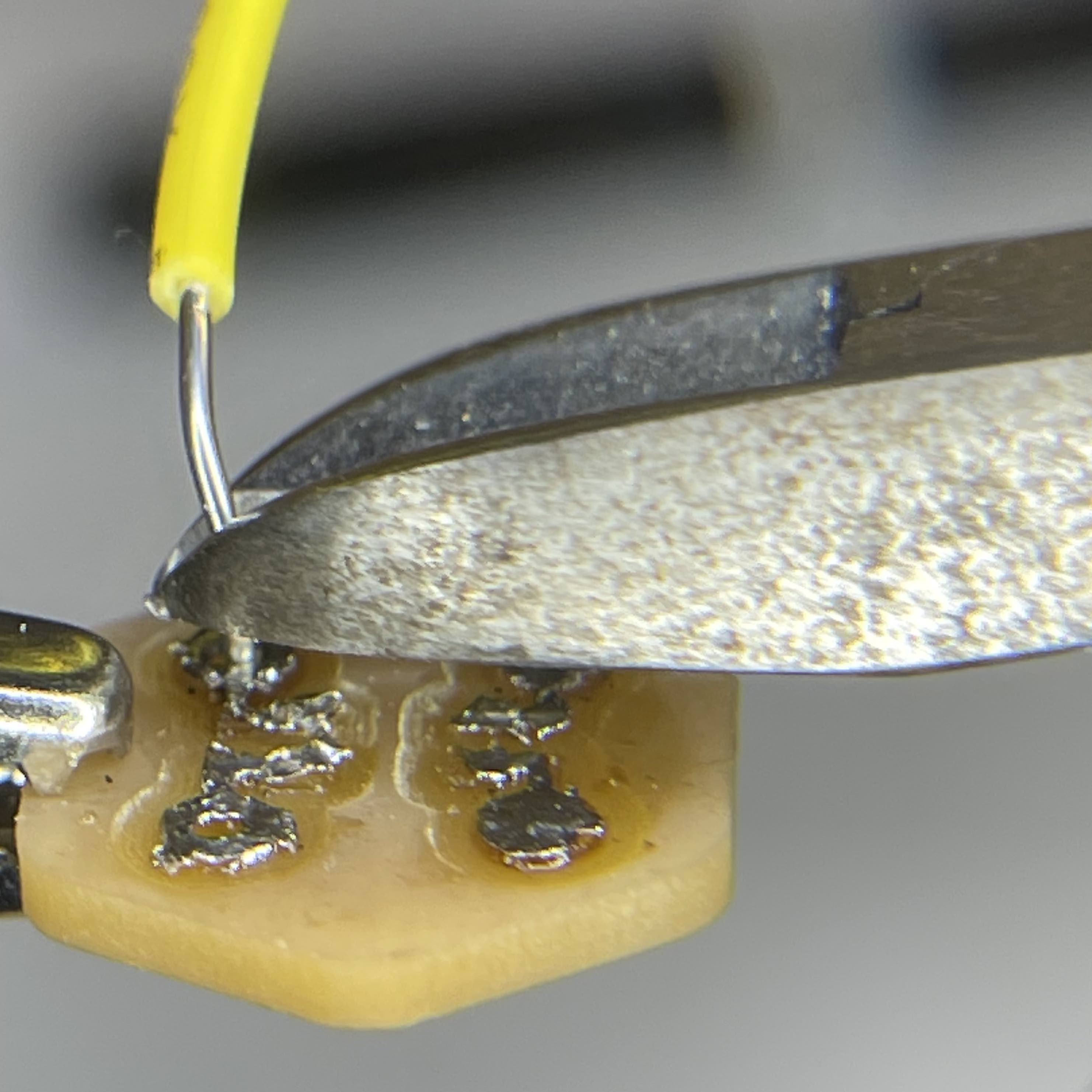
Step 6: Solder the Digital In (front side) and Digital Out (back side)
To do this, cut a 4" piece of wire and sand the very end of it. Then, using tweezers, wrap the exposed copper around to create a coil.
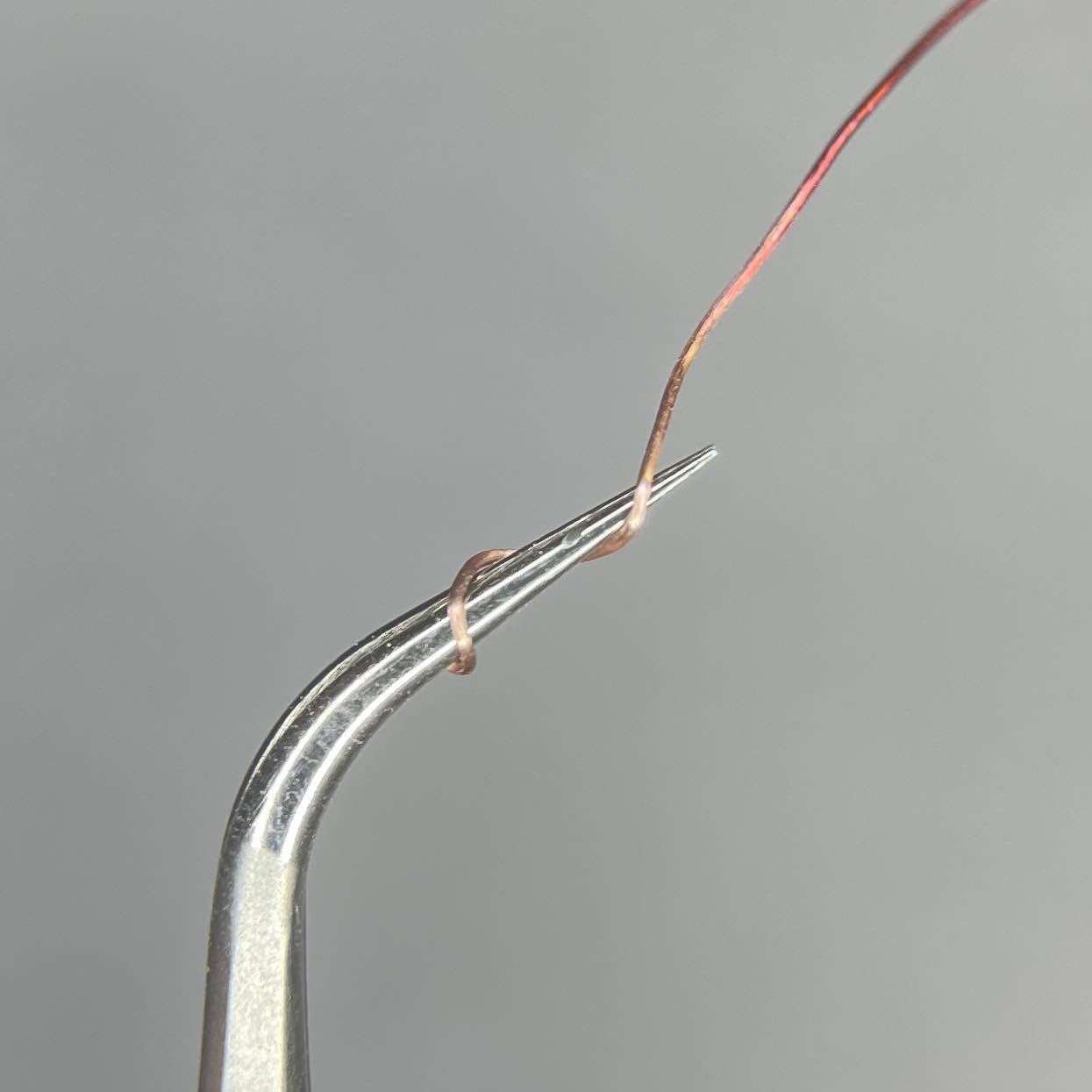
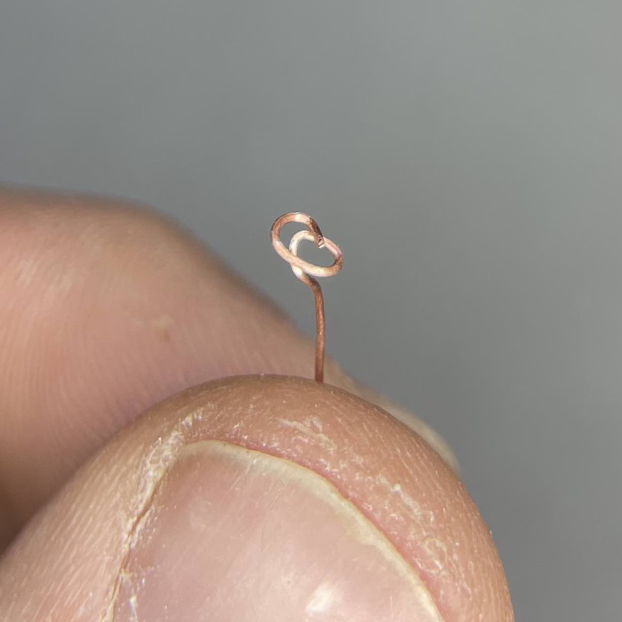
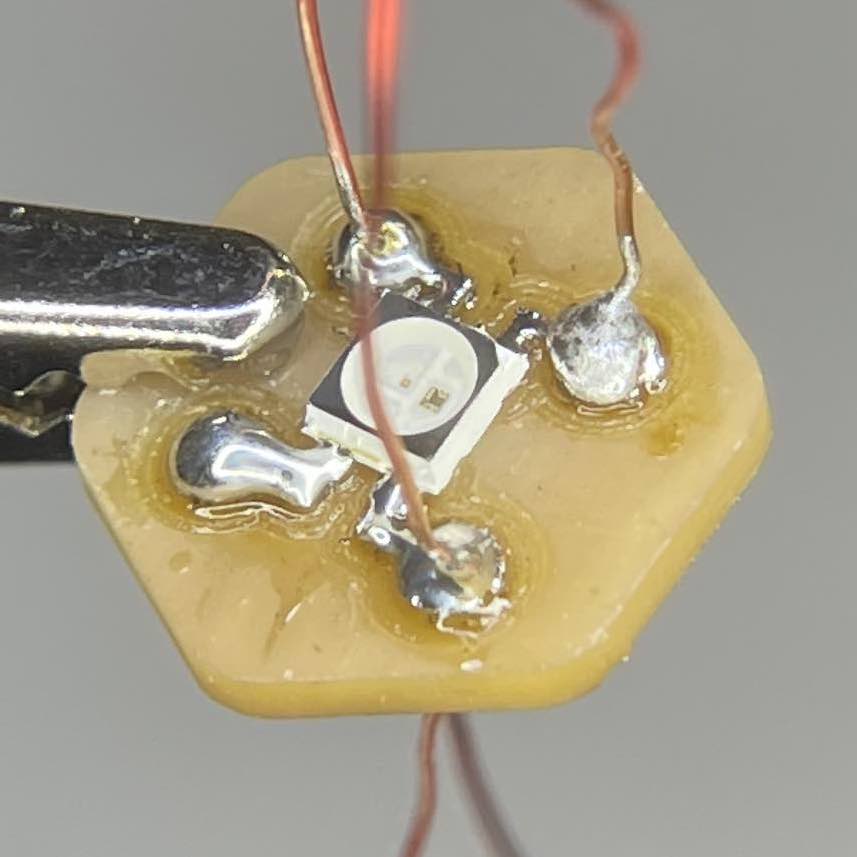
Then flatten the coil so it can sit on the digital in pad (front side) with the use of helping hands. With it there, press it down into the solder with a soldering iron. Push up slight on the helping hand as you move the solder iron away to allow it to harden in place. Repeat on the other side for digital out.
Programming
You may have noticed I said nothing about wiring/connections. That's because this is incredibly simple. Pick any digital pin for the information signal (I chose 3), then you connect VCC and Ground.
To program this board, I created a very simple loop based on an Arduino library that usually cycles colors on a neopixel ring. However, I just alternate the two LEDs. I will add more information when I get the input working to provide code to select specific neopixels and assign color.
#include "Adafruit_NeoPixel.h"

#define PIN 3
#define LEDS 2

Adafruit_NeoPixel strip = Adafruit_NeoPixel(LEDS, PIN, NEO_GRB + NEO_KHZ800);

void setup() {
 strip.begin();
 strip.show(); // Initialize all pixels to 'off'
}

void loop() {
 strip.setPixelColor(0, 255, 0, 0); //RED
 strip.setPixelColor(1, 0, 255, 0); //Green
 strip.show(); //Show The Color
 delay(1000);
 strip.setPixelColor(0, 0, 255, 0); //Green
 strip.setPixelColor(1, 0, 0, 255); //Blue
 strip.show(); //Show The Color
 delay(1000);
 strip.setPixelColor(0, 0, 0, 255); //Blue
 strip.setPixelColor(1, 255, 0, 0); //RED
 strip.show(); //Show The Color
 delay(1000);
}


