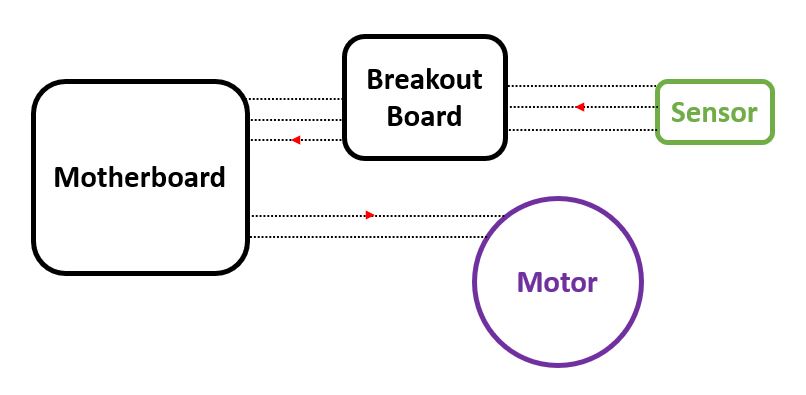
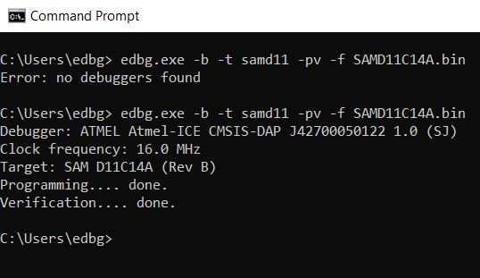
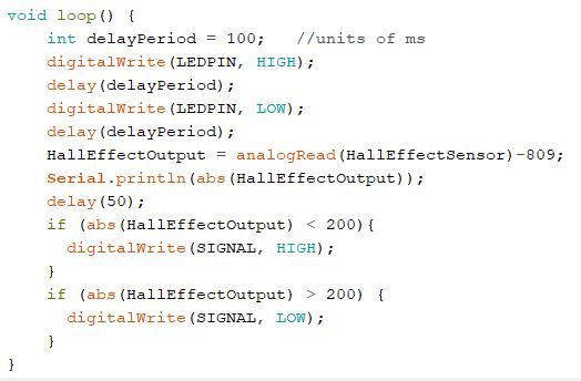
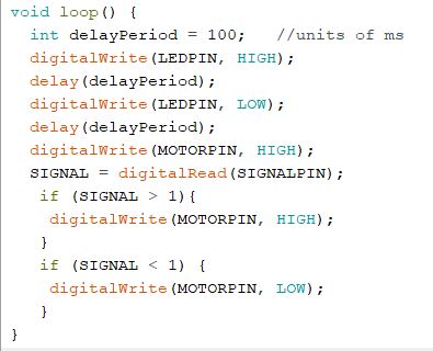
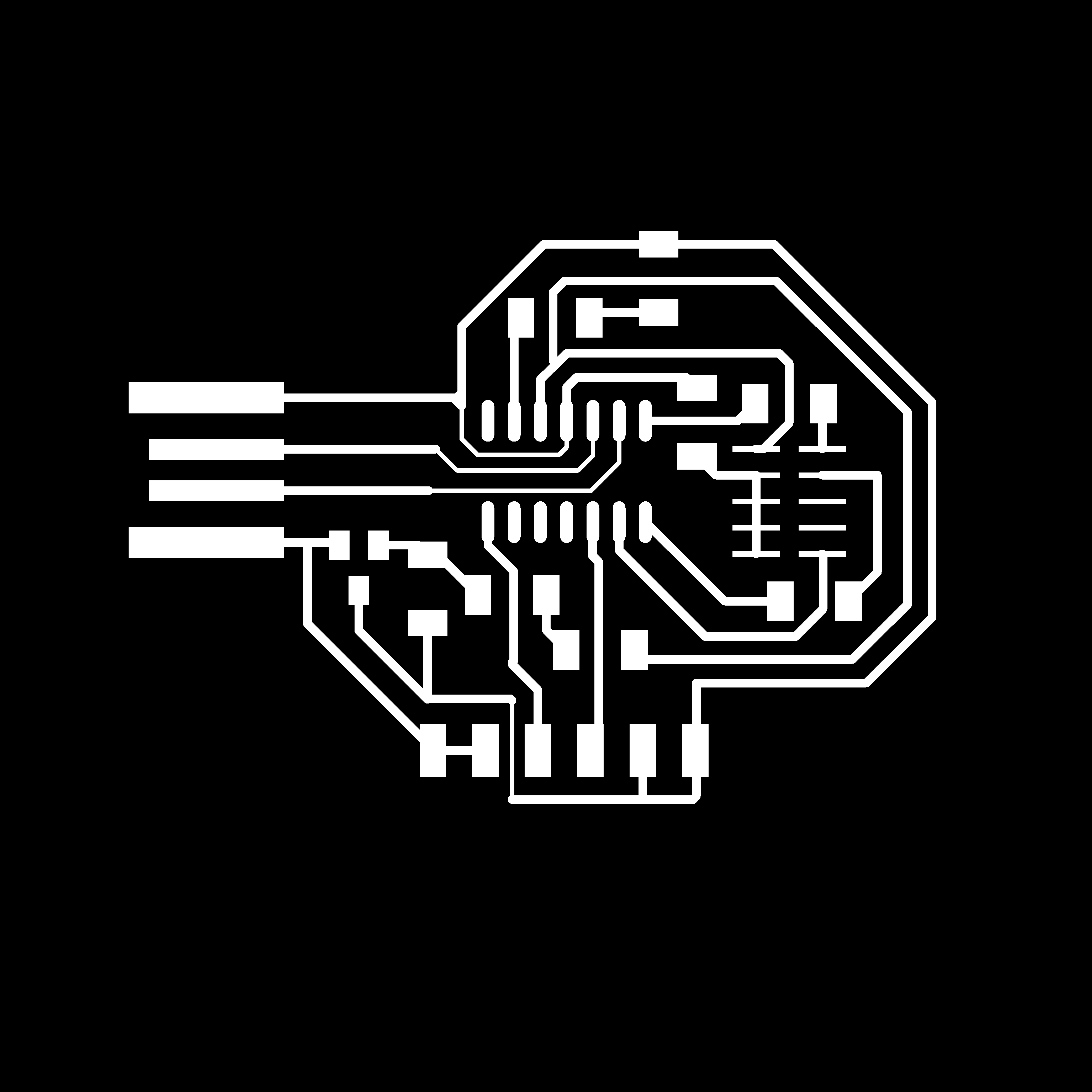
My breakout board incorporated a SAM D11C microcontroller, 10-pin programming header, a digital LED circuit, and connection jumper to transmit and receive signals. The PCB can be powered by either the USB or jumper connection. I added the LED circuit for visual confirmation that the board was programmed. I designed this board in Eagle through Fusion 360.
I forgot to set design rule clearances in Eagle and did not realize this until I imported my trace .PNG file into mods, which showed numerous traces that would not be milled between. After returning to Eagle and setting design rules to 15.7 mils for the 1/64 in end mill, I had to make significant changes to my design. I could no longer run traces between pads of the programming header or the voltage regulator. This resulted in a handful of zero-ohm resistors being used as bridges. The CAD file for my break out board is hyperlinked to the image to the left.
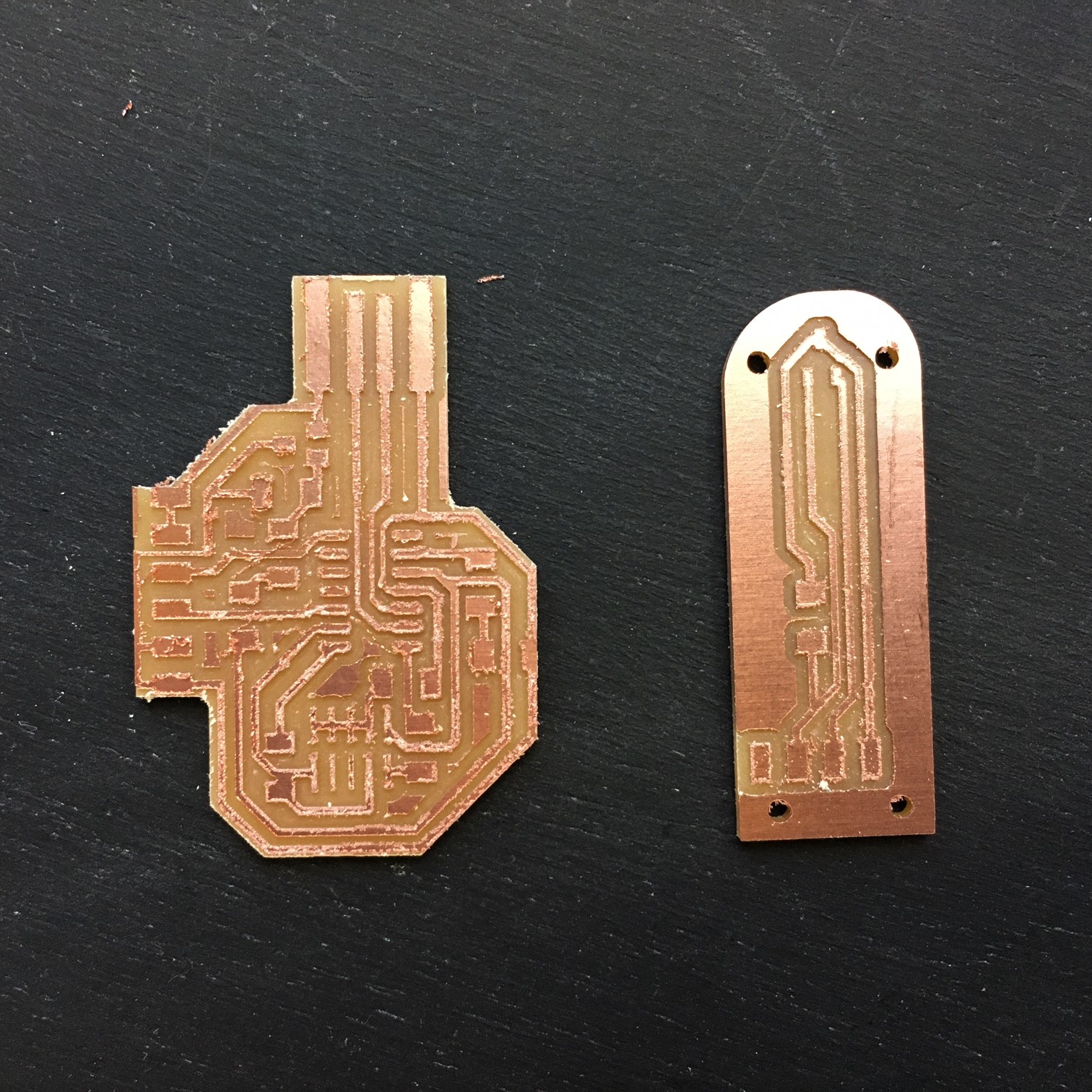
Even after setting design rules, mods still refused to mill between several pads and traces due to limited clearance, so I modified the tool diameter to 13 mils to give the illusion of adequate clearance. I did not realize until after milling, but there was still one pad and trace that were not milled between, which required modification by hand post milling. I milled both of these boards on the Roland-SRM20 micro mill in the EECS lab.
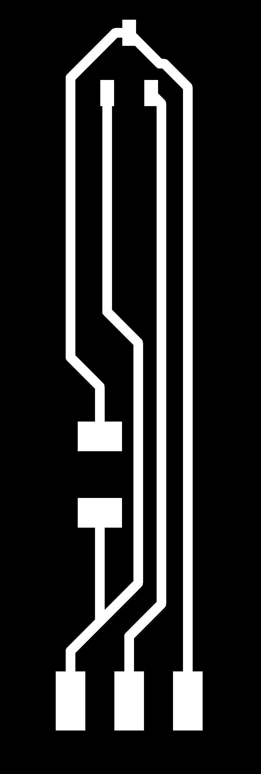
The .PNG trace and outline files for both boards are hyperlinked below, along with images of fabrication steps. The CAD file for my Hall Effect sensor is hyperlinked
here.


Post Milling

Weeding/De-Burring
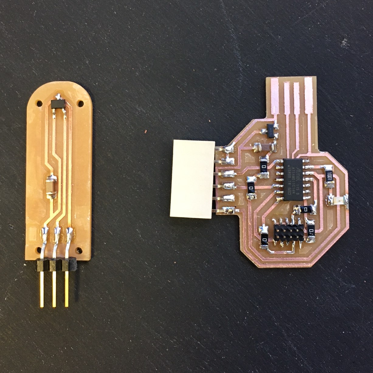
Stuffed
