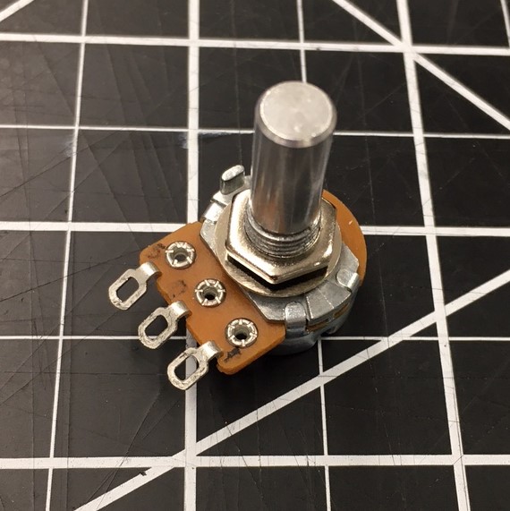
Based on my lessons learned from week 5, I designed and fabricated a new PCB incorporating a MOSFET and a potentiometer to control a 5 V DC motor. The board also included a SAM D11C microcontroller, 10-pin programming header, and connection jumper to receive external signals. I designed this board in Eagle through Fusion 360. Adding the potentiometer was a significant modification from my week 5 board.
Adding the potentiometer to the broad was a major modification. I had to create a new component in Eagle with the correct footprint and pin designation. See Takeaways section for link to a guide on creating a component in Eagle.
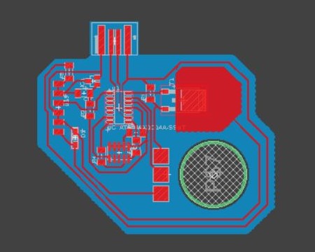
My final board design is hyperlinked to the image to the left.
The PNG trace and outline files for both boards are hyperlinked below.


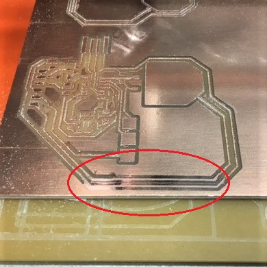
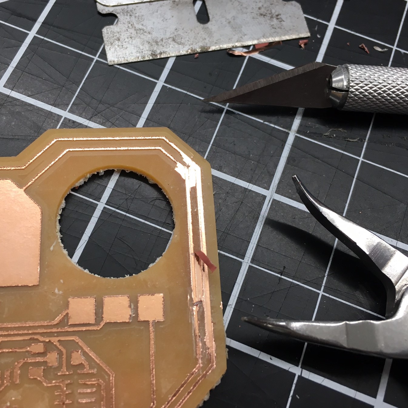
To reuse a piece of stock I had to mill along a board edge. Even with tape adhering the board edge to the bed, it still deformed too much for the copper layer to be completely milled through.
To correct the unmilled traces I thought about re-milling the entire board with a slightly deeper cut depth or resetting the z-axis for this region of the board, but did not based on time constraints and concerns of possibly pulling up traces during a second run. Instead, I created a .PNG file with only the unmilled traces and took a look at it in mods. I immediately realized this wasn't going to work, because it was going to mill through my existing traces. I decided to pull the board off and conduct board surgery while weeding.

Weeding was painfully tedious, but was successful after scorning along the missing trace edges with a razor blade and slowly peeling away the excess copper.

Post Milling
Weeding
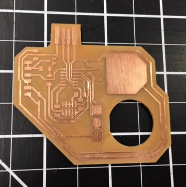
Weeded/De-Burred
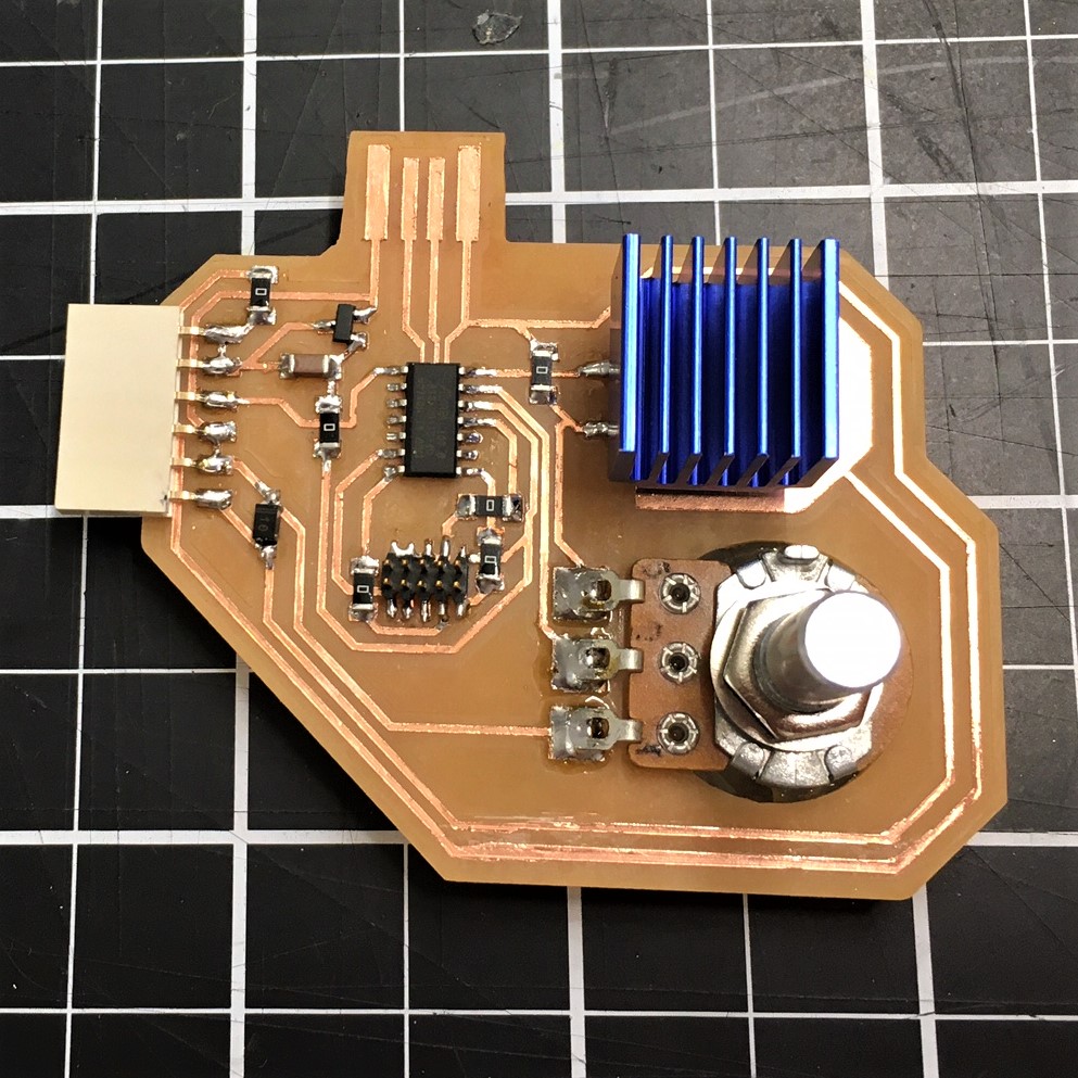
Final Product (Top)
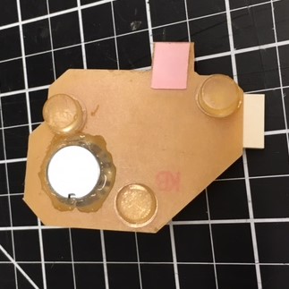
Final Product (Bottom)