Home Final Project Week 1 Week 2a Week 2b Week 3 Week 4 Week 5 Week 6 Week 7 Week 8 Week 9 Week 10 Week 11 Week 12 Week 13 Week 6: Computer Controlled Machining
Week 6: Computer Controlled Machining
6.1 Introduction
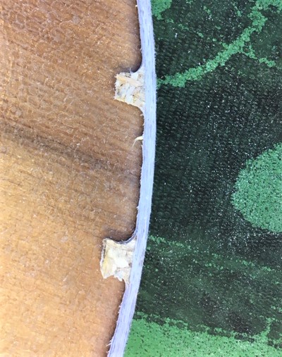
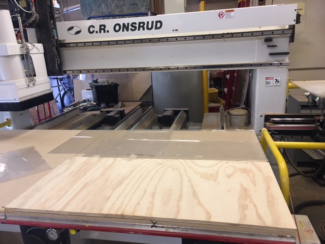
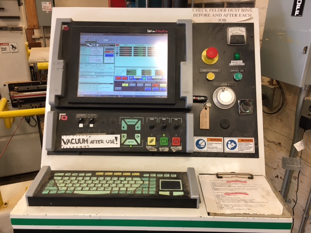
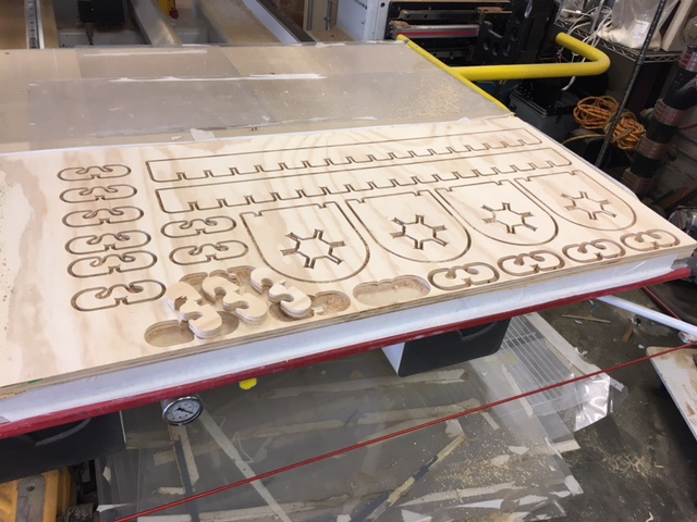
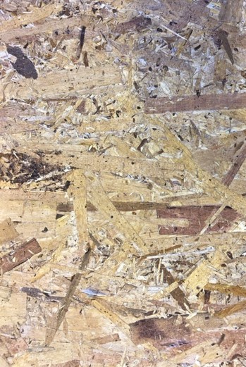
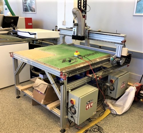
For this assignment we were provided up to 32 sqft of Oriented Strand Board (OSB) to fabricate something big. The OSB is composed of an inhomogeneous mixture of wood scrapes that are pressed together to form a plywood board commonly used in lumber construction. The sheets provided to the EECS section also contained a weather resistant coating on one side. For milling this material, the EECS shop has a 3-axis Avid ShopBot mill, which is capable of three-dimensional milling within a 4 ft by 4 ft by 1 ft volume. Due to the inhomogeneous nature of OSB it is not well suited for milling, so I decided to use a section of finished plywood that I had in my garage in hopes of achieving a better surface. The images below from left to right show the OSB provided, the Avid ShopBot, and the plywood I planned to use.
6.3 The Design
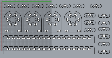
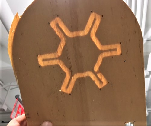
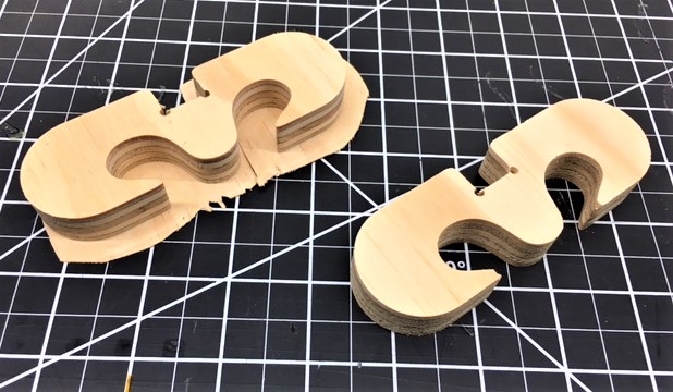
I used this week's assignment to design and fabricate the supporting frame for my final project. Using Fusion 360 I created the design shown to the right, which is hyperlinked to the CAD file. My design incorporated three different components: two long boards with notches every two inches to serve as the frame's base, an array of two-sided retainers to hold wire coils in place, and four arches that serve as frame crossbars and for holding the retainers.


To create dog bone joints, points were added at the interior corners of my CAD file prior developing the G-code in MasterCAM. These points were used for creating the first tool path.


With assistance from Chris in the architecture shop, the G-code for milling my components was created in MasterCAM. The milling process was divided into the following five tool paths:
      1) Hole Drilling (1/8 in) for dog boning at connection points;
      2) Internal Contour (1/4 in) of crossbars;
      3) Remachining (1/8 in) of internal crossbars;
      4) Outer Contour (1/4 in) of all components;
      5) Remachining (1/8 in) of outer contours.
Tool paths using a 1/8 in diameter end mill were set for a feedrate of 250 in/min and spindle speed of 18000 rpm. Tool paths using a 1/4 in diameter end mill were set for a feedrate of 350 in/min and spindle speed of 15000 rpm.


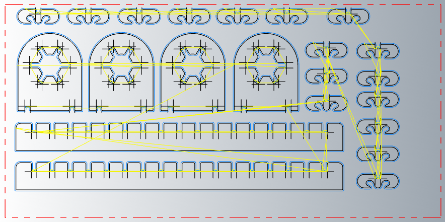
The image to the left shows the anticipated tool path for the final remachining operation. This tool path used a 1/8 in diameter end mill to finish all dog bone connections.


6.5 Take Aways