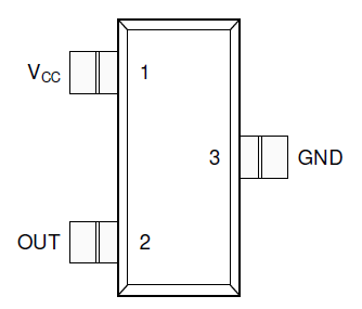
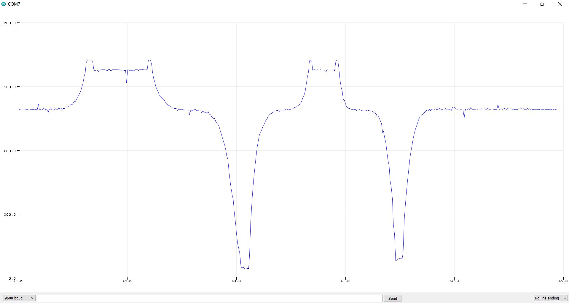
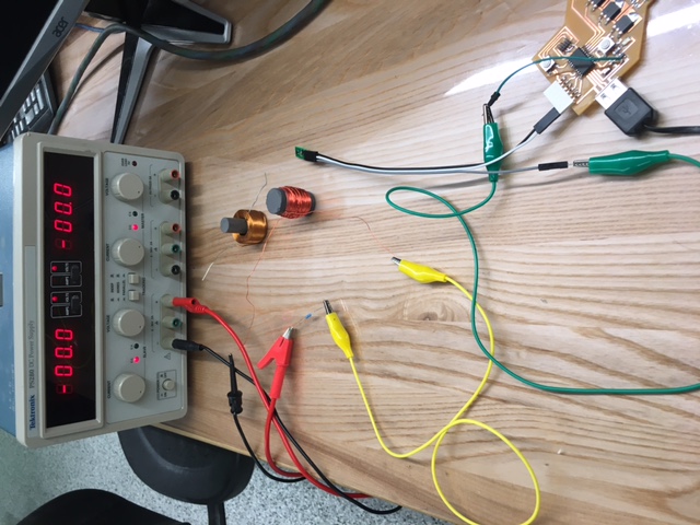
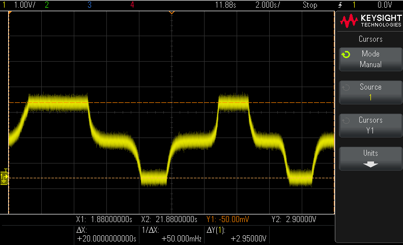
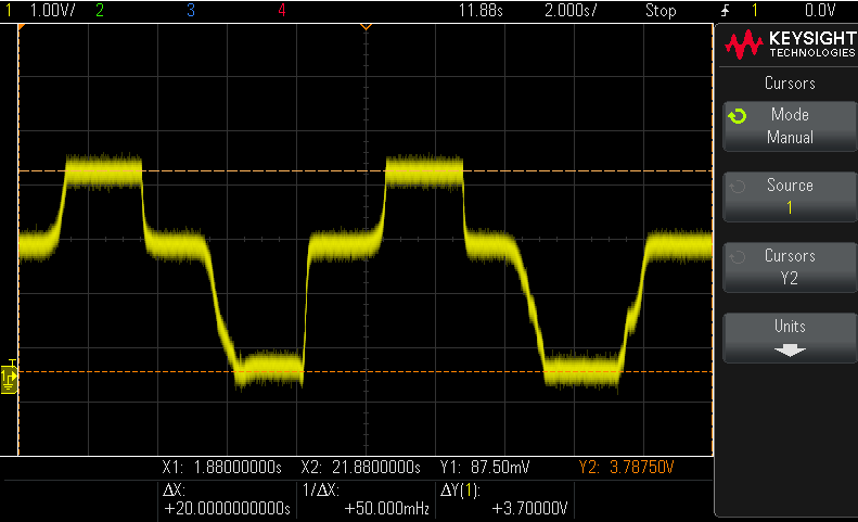
Having a Hall Effect sensor that I was confident would work, I set out on designing and fabricating my own Hall Effect sensor with components available from the fab lab library. My design was built around the Allegro's A1302 Hall Effect sensor, which is a single axis magnetic field sensor that operates with 5 V. The functional block diagram below is from the component's
datasheet.

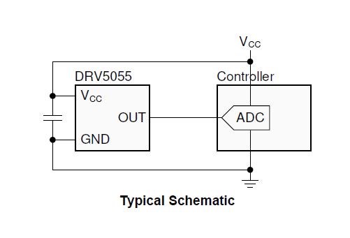
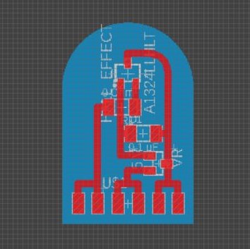
Using Eagle through Fusion 360 I generated the schematic for my sensor board. I based the circuit on requirements from the component’s datasheet. My CAD design and .PNG milling files are hyperlinked to the below images.
While designing my Hall Effects sensor I was fully aware that the Allegro sensor required an input voltage of 5 V, but I still included a voltage regulator footprint in my design. I based this off the theory that I could use a 5 V regulator to ensure more consistent voltage being provided to the sensor. It turns out this was a silly consideration and there aren't even 5 V regulators in the fab lab inventory. So, I ended up soldering a jumper wire across the voltage regulator pads. When I redesign my sensor for the final project, I will remove this component and add vias to serve as mounting points for the board.

Post Milling
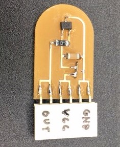
Final Product
