Output Devices
add an output device to a microcontroller board I am designed, and program it to do something.
Concept
My final project will design haptic module. Therefore, in this assignment, I want to output analog signals and control haptic module by using PCB designed by myself.
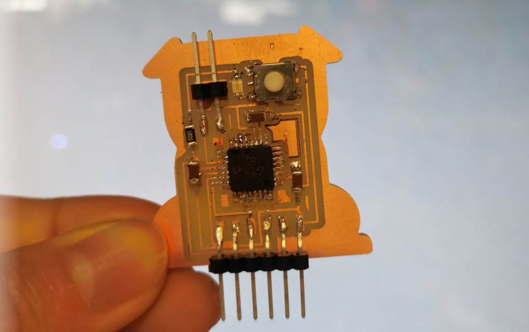
Designed PCB
I used the PCB designed in Week5-Electronics Design. You can find more information about this PCB by click the link of Week5 website.
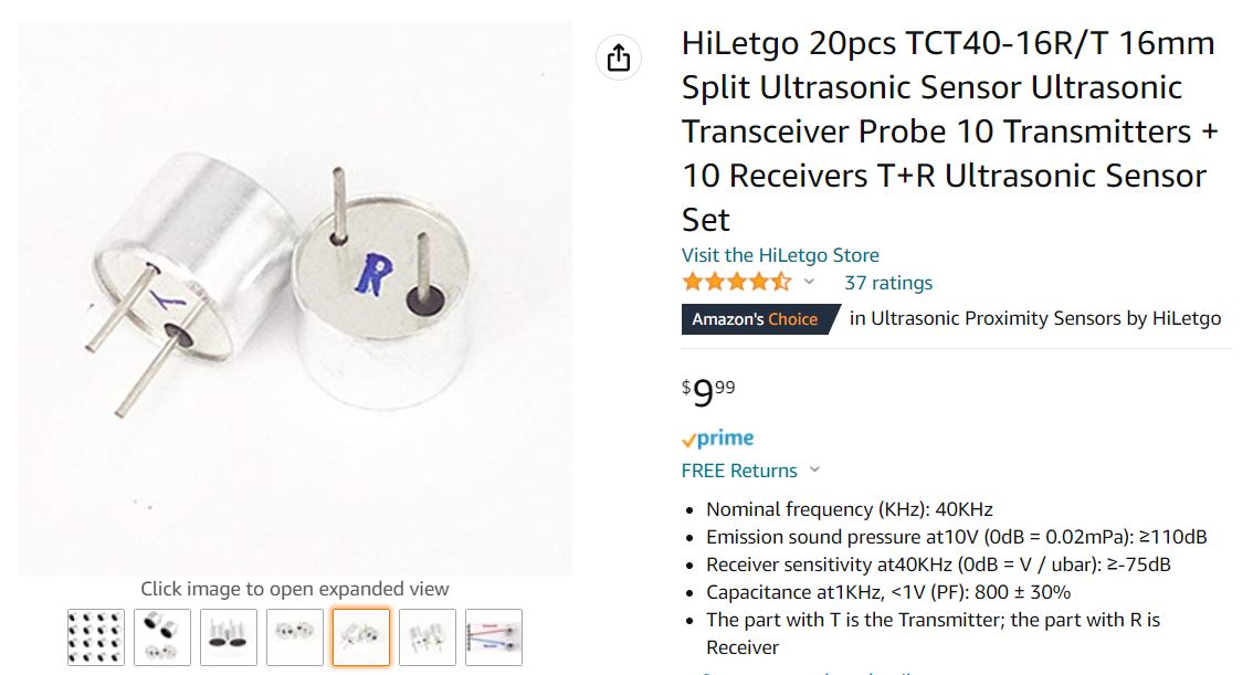
Ultrasonic Transceiver
The ultrasound haptic modular I used is HiLetgo 10 Pairs 16mm Split Ultrasonic Transceiver. And the detailed descrption is this sensor is: Nominal frequency (KHz): 40KHz Emission sound pressure at10V (0dB = 0.02mPa): ≥110dB Receiver sensitivity at40KHz (0dB = V / ubar): ≥-75dB Capacitance at1KHz
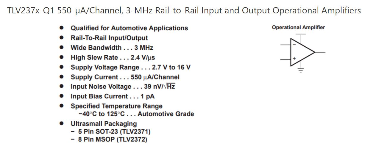
Operational Amplifiers
Operational amplifier (OP amp) plays an important role in the application of analog signal regulation. To make the system work, I added an OP amp between the controller and the output haptic modual.
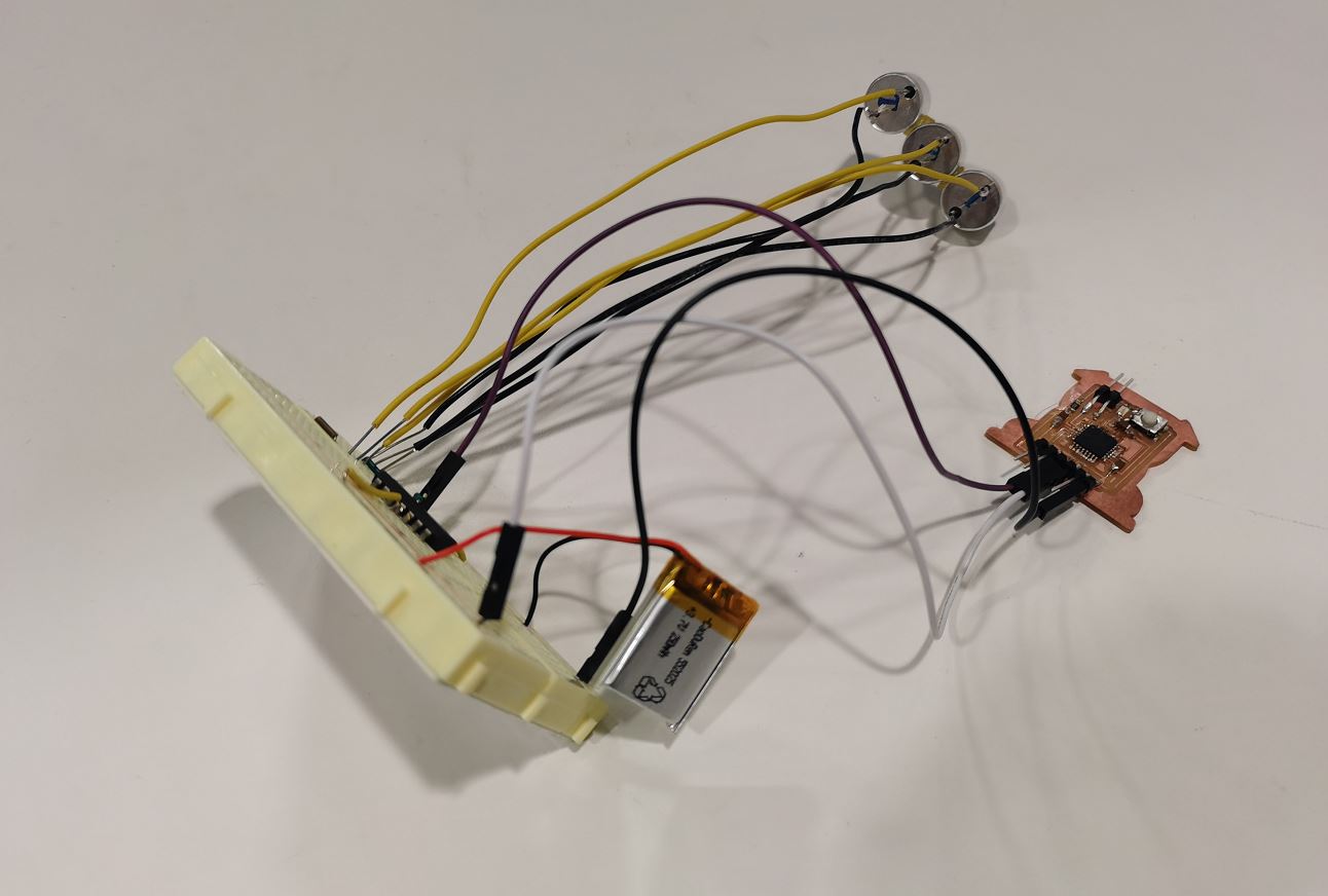
Device
And the image shows the whole device including power supplier, haptic modular, Opamp, and controller. And you can see the demo of this system below! Considering that haptic feedback is relatively difficult to present, I put a napkin in front of the haptic module. And I used "analogWrite(HapticPin1, 128); " in software, and thus haptic output is available only half the time in a cycle. As the image shown in https://docs.arduino.cc/learn/microcontrollers/analog-output, the number in analogWrite() will determine the Pulse Width Modulation. A call to analogWrite() is on a scale of 0 - 255, such that analogWrite(255) requests a 100% duty cycle (always on), and analogWrite(127&128) is a 50% duty cycle (on half the time) for example.