Week 8: Input Devices
"You need more breakout boards" -Quentin
This week we were tasked with measuring something using a sensor. I decided to begin working on my final project, which innocently requires a recording device. What I've come to learn this week is that recording devices (aka spybugs) are quite tricky to make yourself.
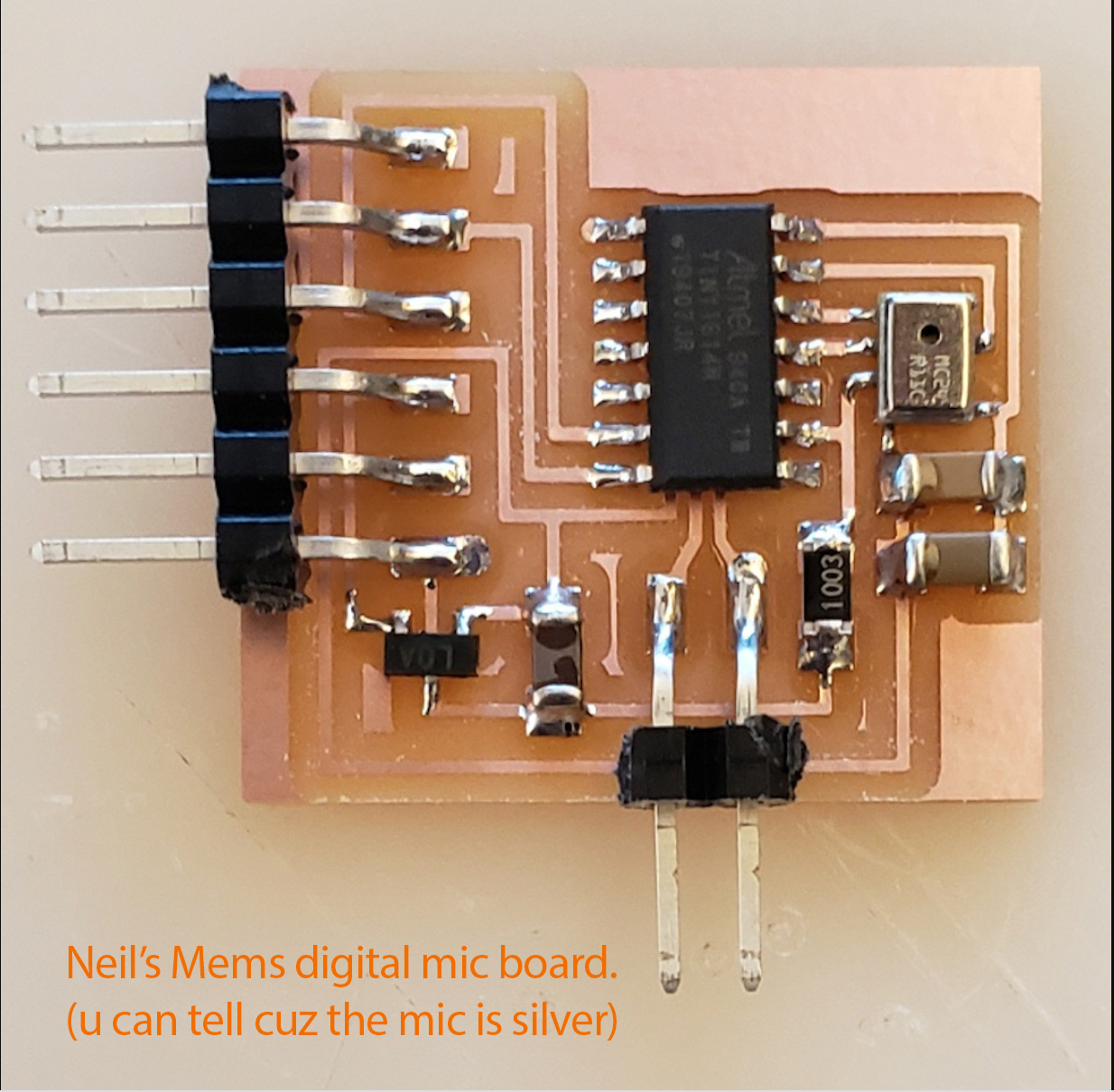
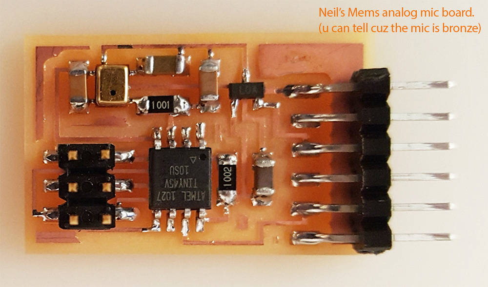
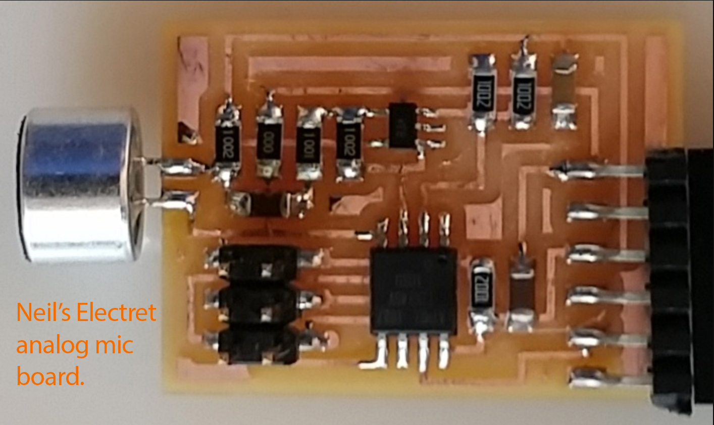
I first looked at what Neil had on his website regarding inputting sound. You can obviously find that info here. Neil had boards using 3 different mics, a Mems digital, Mems analog, and Electret analog. I spent many hours deciphering what the differences between those mics are and which one I should use.
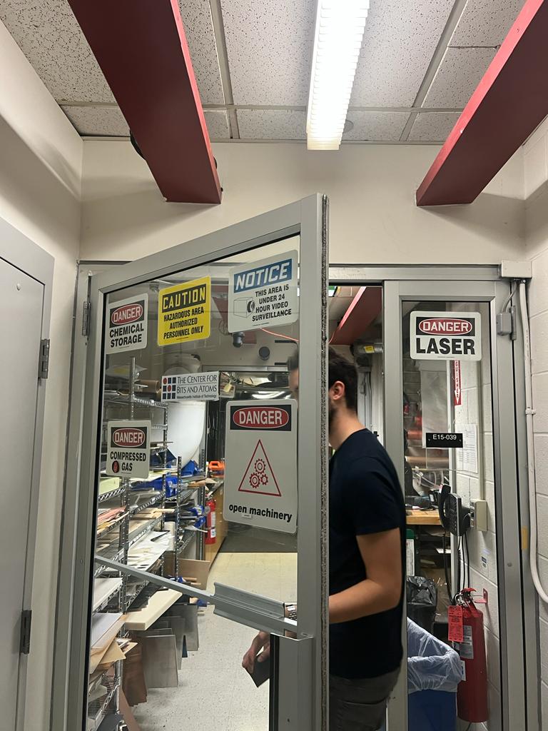
I looked online to try and see if anyone has made a recording device for this class. For some reason I could not find what I was looking for. So I ventured to MIT for office hours. Maybe they had some secret info on spybugs that Harvard wasn't privy to. I felt hopeful when I saw all the caution signs on the door of the lab. Dave and Quentin were both there and explained to me that sound is probably the hardest input to figure out! Yay! (-:
*tap* *no tap* *tap* *tap* *no tap* *tap* Can you hear me? I'm crying.
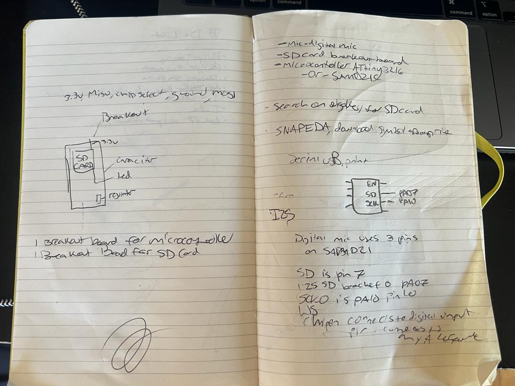
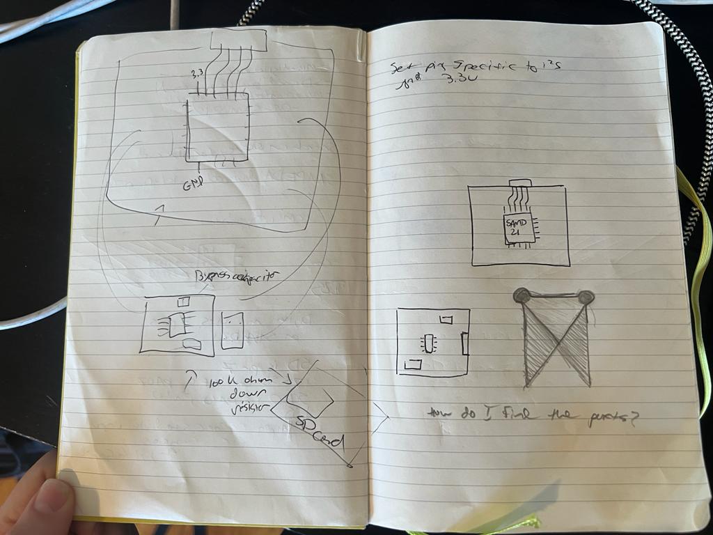
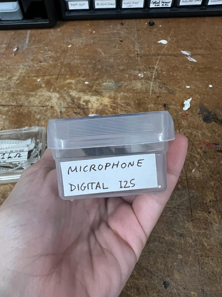
I studied the Mems digital mic datasheet, to try and understand which pin should go where on my microcontroller. (You're welcome to take a stab at reading my notes. Its just a bunch of tiny centipedes to me at this point) Quentin also informed me that I should be using breakout boards for everything. Like pretty much dissect the board into tons of parts so that its modular. I figured for my final recorder+speaker device I'd need a breakout board for the mic, a breakout board for the SD card (because sound uses too much memory to store on a microcontroller) and a breakout board for my microcontroller!
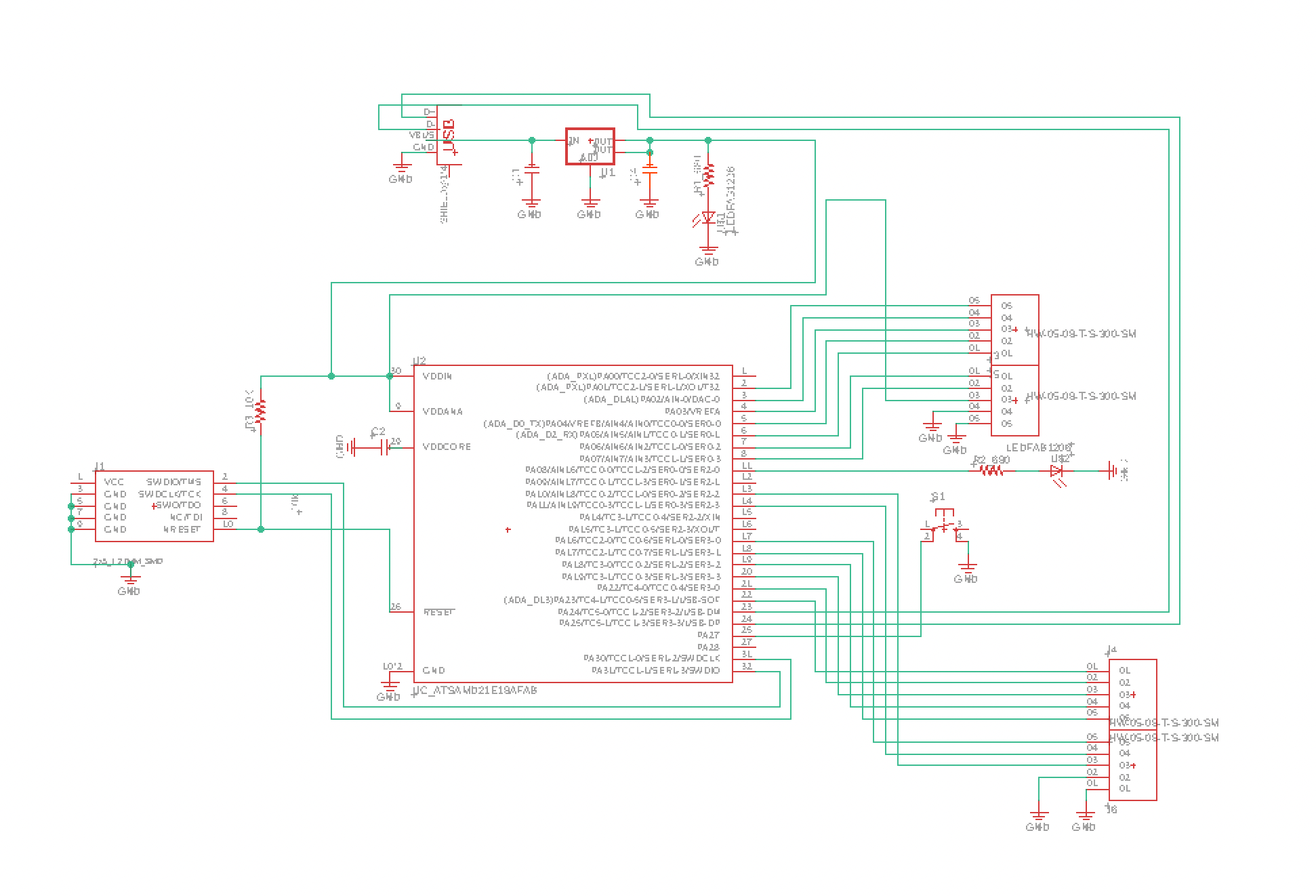
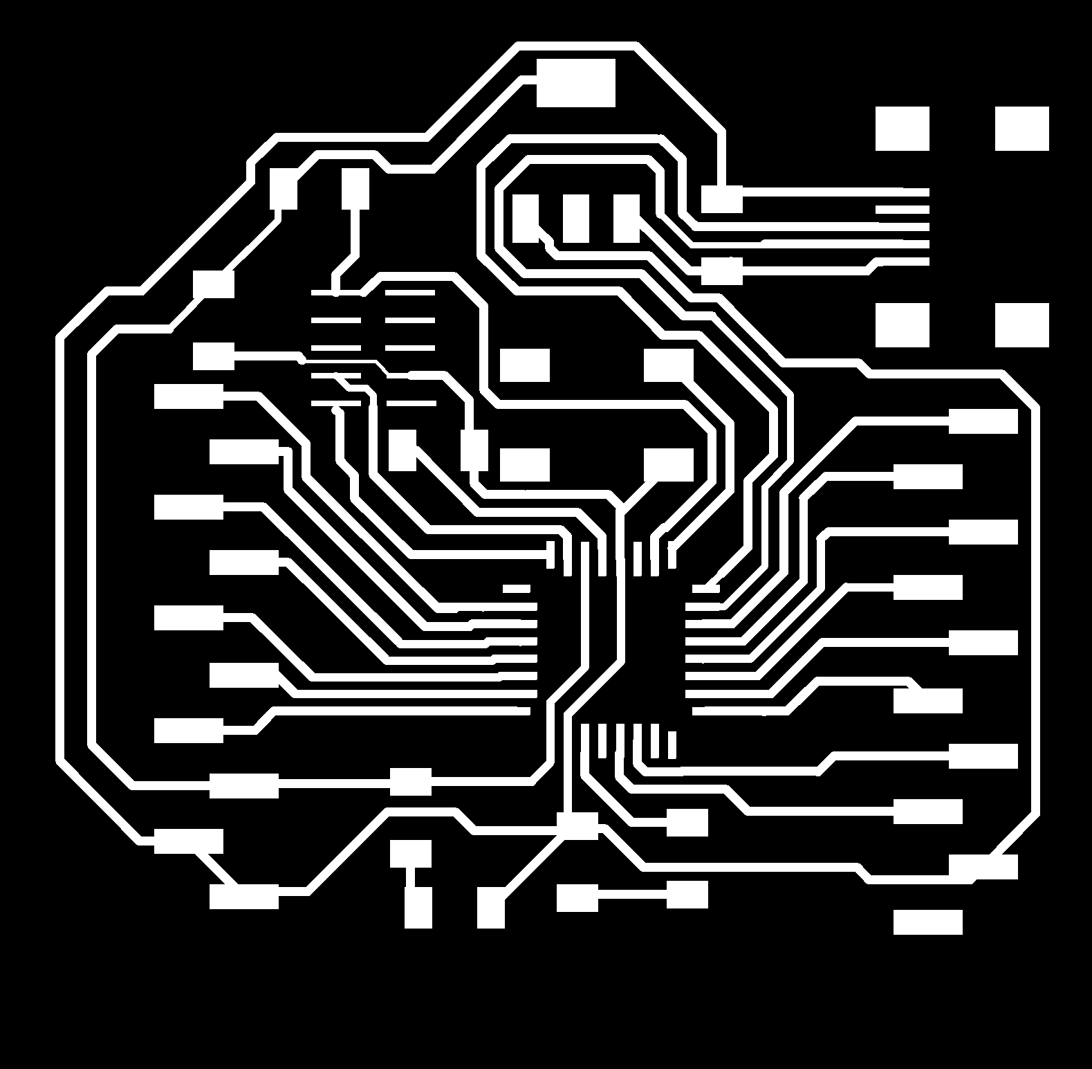
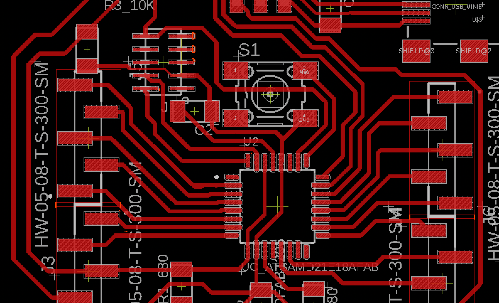
I began by creating a microcontroller board using the SAMD21 and a button (for pressing record). Luckily, Quentin had a SAMD21 microcontroller devkit on his site. Claire had also been working on adapting Quentin's board in eagle. I asked Claire for her files so that I could add a button to the design. Claire kindly obliged because she is a guardian angel sent from the heavens to protect all lost and confused souls. I began the most hateful process of tracing in eagle and eventually achieved the above.
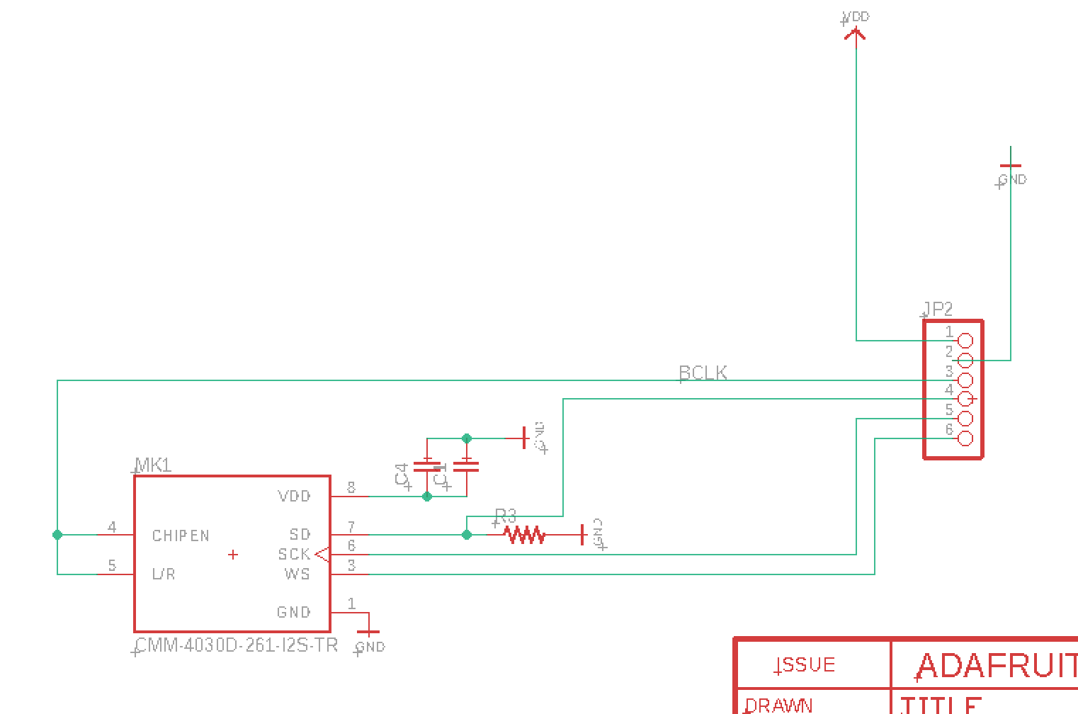
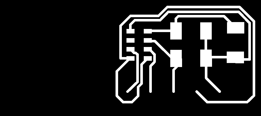
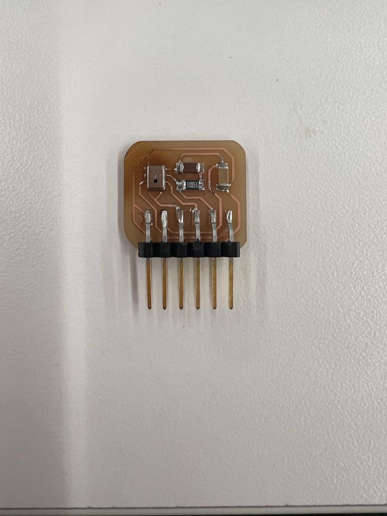
While in Eagle I also designed my microphone breakout board. I used a shortcut by downloading Adafruit's microphone breakout board schematic. You can find that under Technical Details for the product here. I adapted it by switching out the mic they had for the digital mic I'll be using which has 8 pads on the bottom. I referenced my notes from the mic datasheet to know which pads should go where on the 1x6 pin header I'm using.
I tried milling my boards but the SRM-20 was acting buggy and it was getting late. I was also still recovering from a cold. I went home and pondered my stupidity. As I lay in bed looking into darkness of my eyelids, all I could see was the spinning and grinding of the 1/64th inch endmill. This week felt like information was thrown at me from so many different directions and it was a scramble to try to make sense of everything. It took hours for each concept to compute. But I feel confident in the direction I'm going in for my final project.
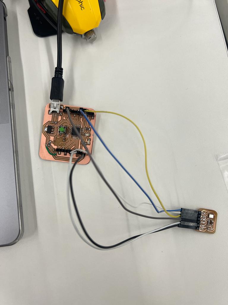
UPDATE
Samd21 dev board works! Mic does not (mics suck).