Brian's HTMAA Diary 2024
Week 04: Electronics Design
Group Assignment
For Electronics Design week, we got a tutorial from Quentin on using the multimeter and oscilloscope.
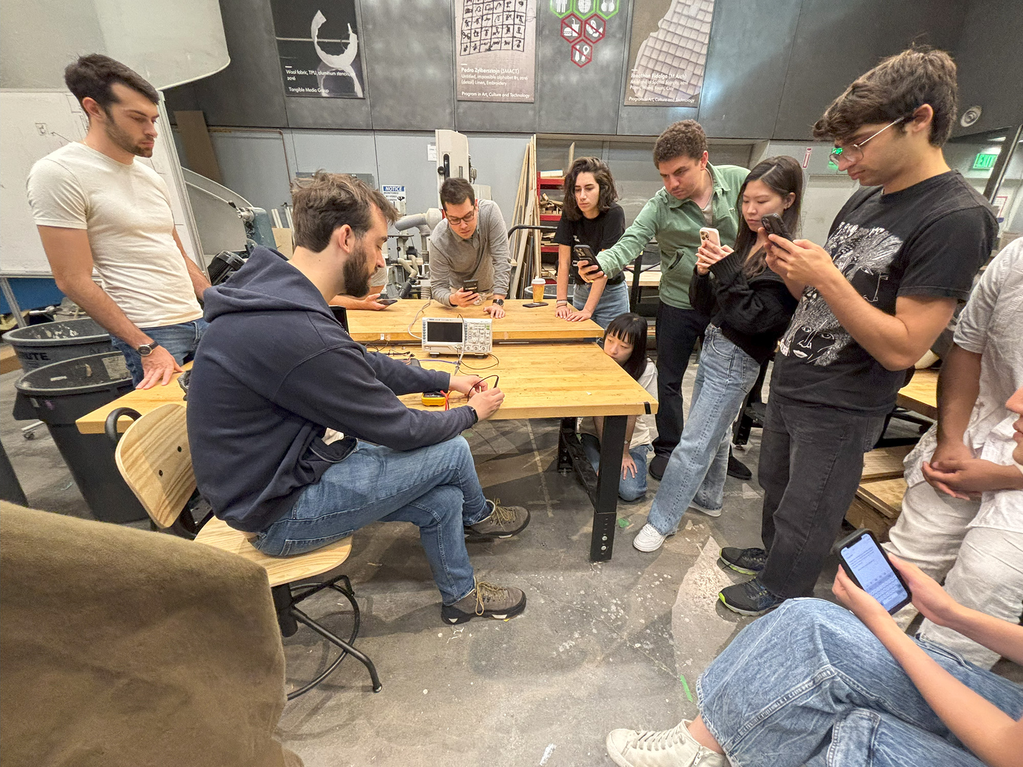
Multimeters can measure voltage, current, and continuity, which is whether to conductors are connected. We were warned about working with things above 20 volts, as it could lead to electrocution.
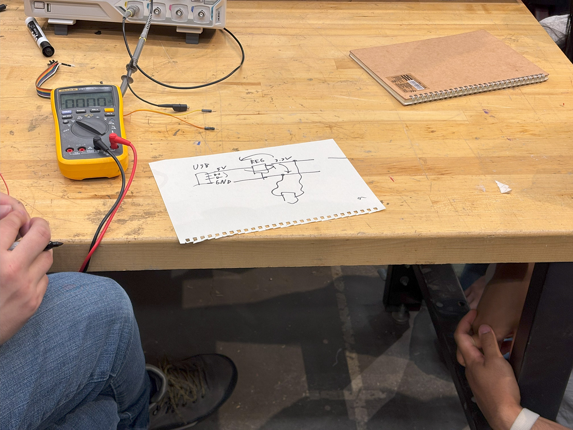
We also learned a bit about using a voltage regulator to interface with USBs.
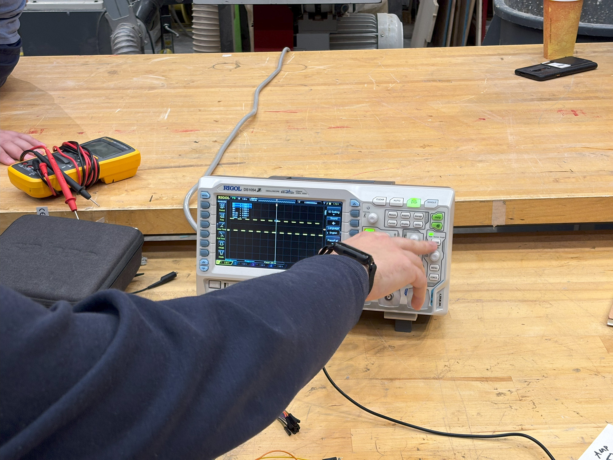
We then tried out different ways of measuring voltage with the oscilloscope and digital USB oscilloscope. While the analogue oscilloscope only has 4 channels, the USB oscilloscope can go up to 8 channels.
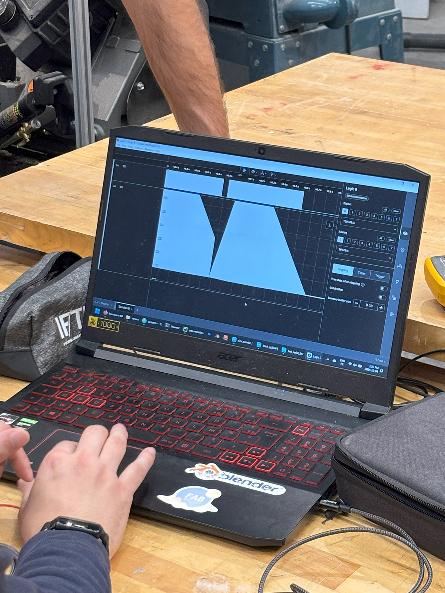
We were also warned that the USB oscilloscope could only be used as a logical analyzer for signals.
Individial Assignment
For my individual assignment, I wanted to recreate this flash trigger my friend made with an ESP32 development board.
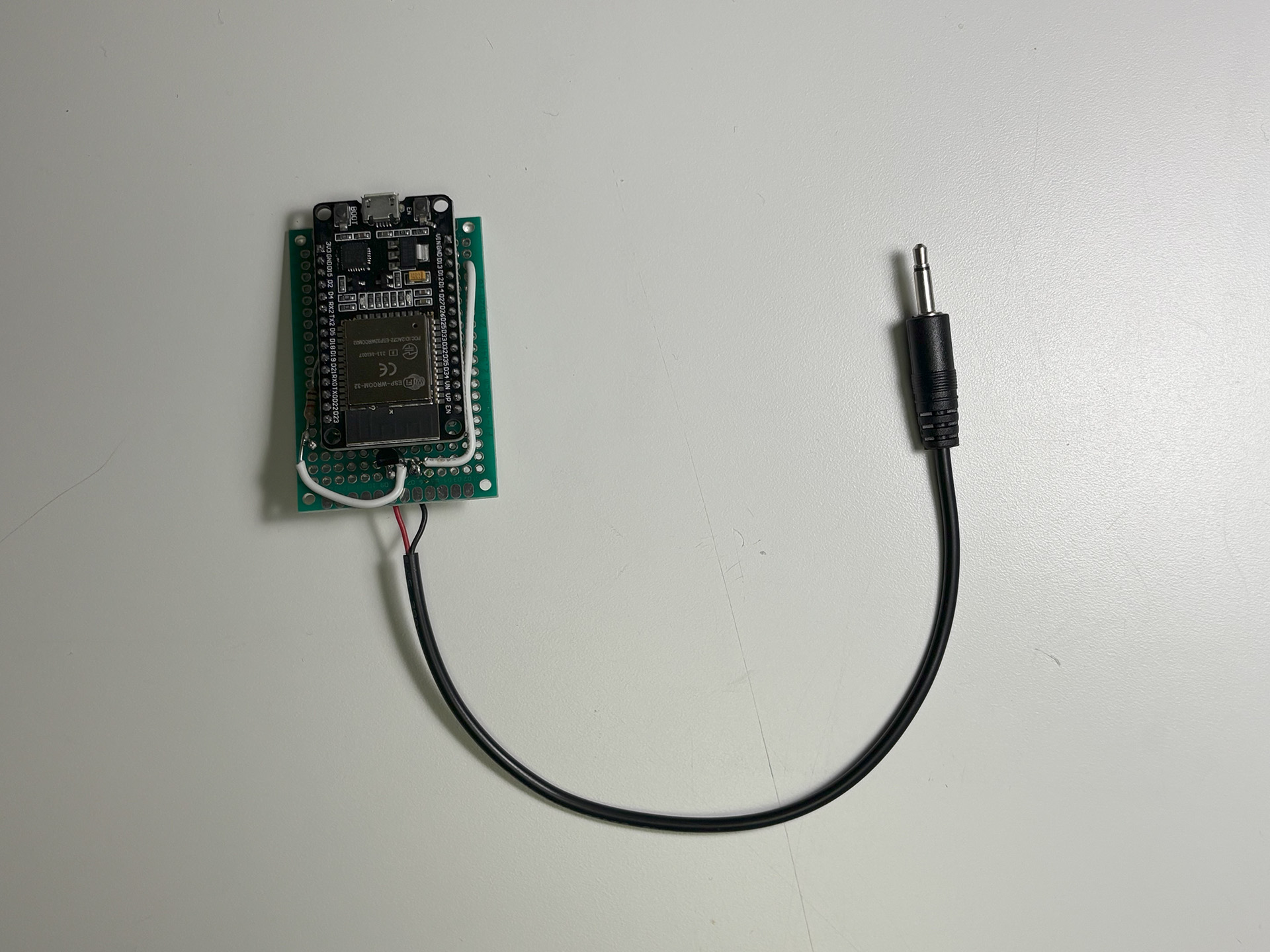
I started by copying the circuit one-to-one, but I realized that since I only am using the ESP32 microcontroller, there were no peripherals for things like wi-fi, USB, etc.
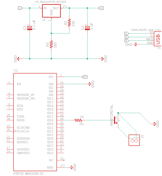
I ended up having to do more research into voltage regulators, as the actual circuit wasn't complicated, but getting power to the microcontroller confused me.
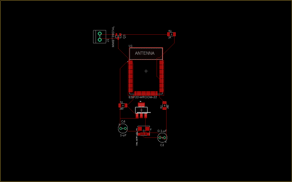
I'm still unsure how to attached the 2.5mm plug, so I attached a terminal for the interim.