Web Design, Version Control, and Final Project Brainstorm
Laser & Vinyl Cutting
3D Scanning and Printing
Make Something Big
Molding and Casting
Electronics Production
Electronics Design
Embedded Programming
Input Devices
Output Devices
Networking & Communications
Interface and Application Programming
Final Project
How to Make (almost) Anything
4.140
Omar AlDajani
Fall 2020
Disclaimer: I have never made a website, and for the most part, don't know what I'm doing.
The aim is for me to document my work. Let's see how this goes.

This is a photograph I shot on February 4th, 2018. It serves as a metaphoric reminder to stand strong. No matter how hard it rains or snows, the city of Boston with all its skyscrapers and tunnels will weather the storm. In addition The Prudential Center lit up with the words "NOT DONE" cheering on the New England Patriots during 2018 Super Bowl, where they won for the 6th time! We too shall weather the hurricane of information that is: How to Make (almost) Anything! and we too will certainly NOT be DONE when it's over!
Final Project:
I made a hands-free robot stroller which my wife called the "Strobot". It makes you feel like you have telekinetic psychic powers, and it feels abdnormally weird yet nice to "push" without pushing!
Here is my project showcase:
and a Youtube link to share, like, subscribe, etc:
You can view technical details and the making process here.
Some advice: from day 1, try to keep every assignment relevant to your final project. I only began doing that when we reached input devices. I had many unknowns along the way simply because I began the actual work a little late. Don't misunderstand, I really did put time and energy into the final project every single week, it just would have been much easier to get there if every assignment was a direct contribution to it. You should really have a good idea of what you want to do early on.
Overview
I decided to make this overview for prospective students to help them see what to expect, especially if they were like me, completely new to everything this class had to offer. This is also a summary of all that I made in this class to ease navigation to the item of interest in the toggle side bar. Below you will find what I did, and what was involved to reach there. Each of these assignments were done in 1 week except Output Devices and Networking & Communications where we had 2 weeks each due to holidays.You can click on any of the headings below to go to that week's page with all the details. Here we go:
Web Design, Version Control, and Final Project Brainstorm
This week was overwhelming. I made this website. I learned a bit of html to do so, and then I had to learn about Git to maintain and update it.Laser & Vinyl Cutting:
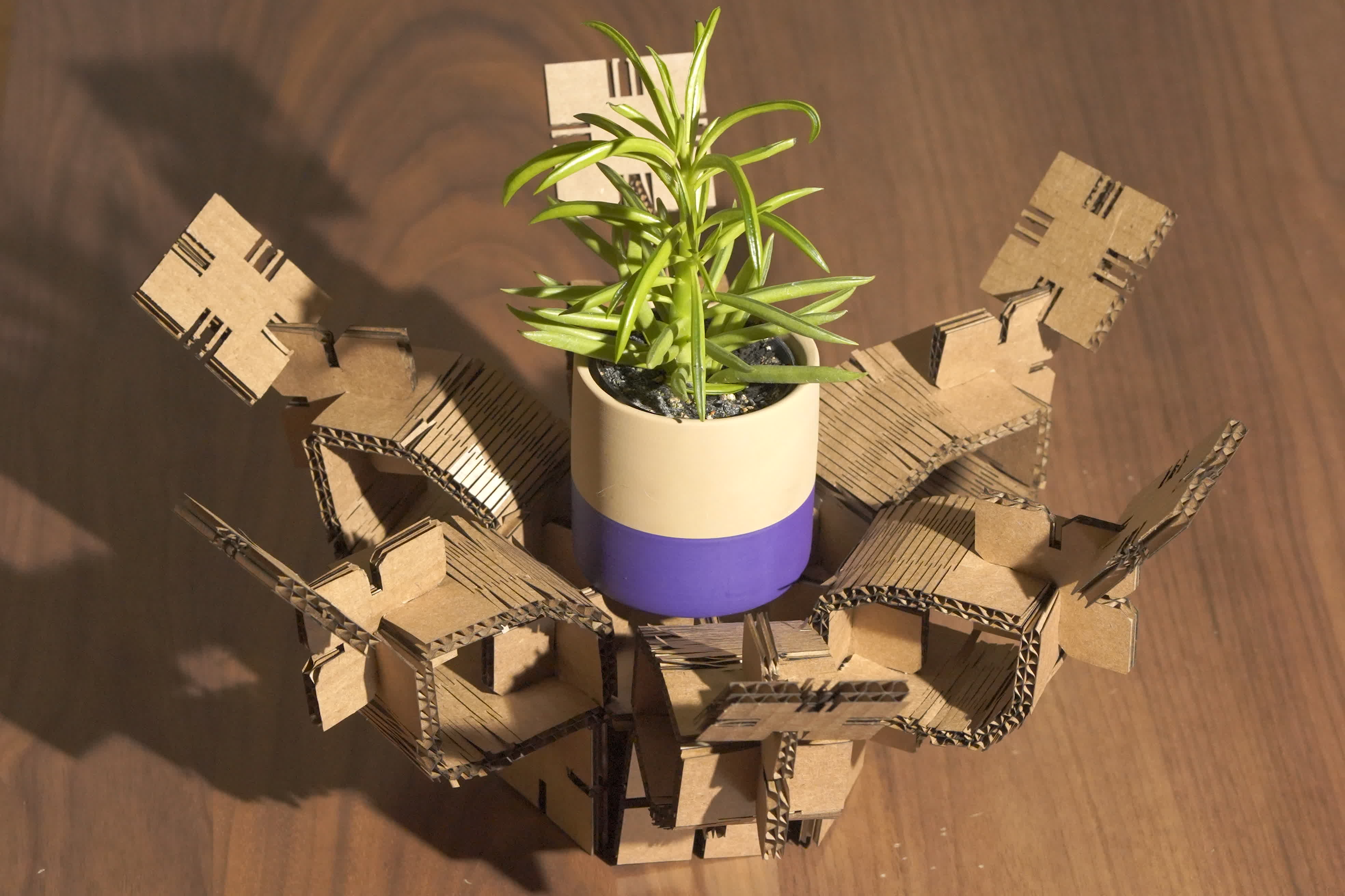
I laser cut a construction kit that can make things based on your imagination. It is not meant to make anything specific. I had fun with it with my wife and daughter and made a few wacky things.
For the vinyl cutting, I cut a Pokeball, cuz we gotta catch'em all, right?
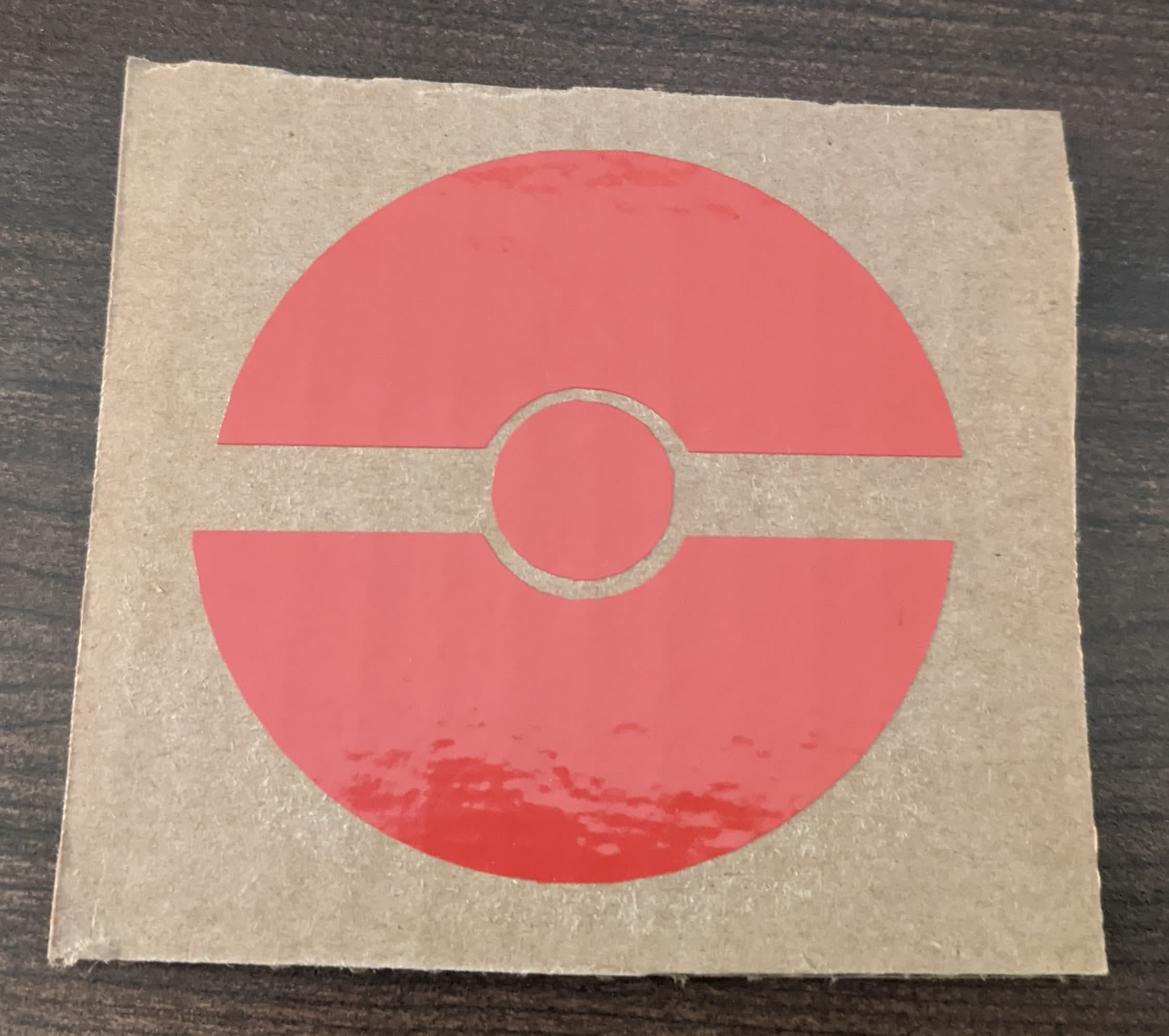
These involved 2D design and learning how to use a laser cutter along with its advantages and limitations.
3D Scanning and Printing:
I 3D scanned my face and a broom (which I also printed), but the highlight is the 3D print. I made a multi-jointed rattle toy for my daughter which she absolutely loves.
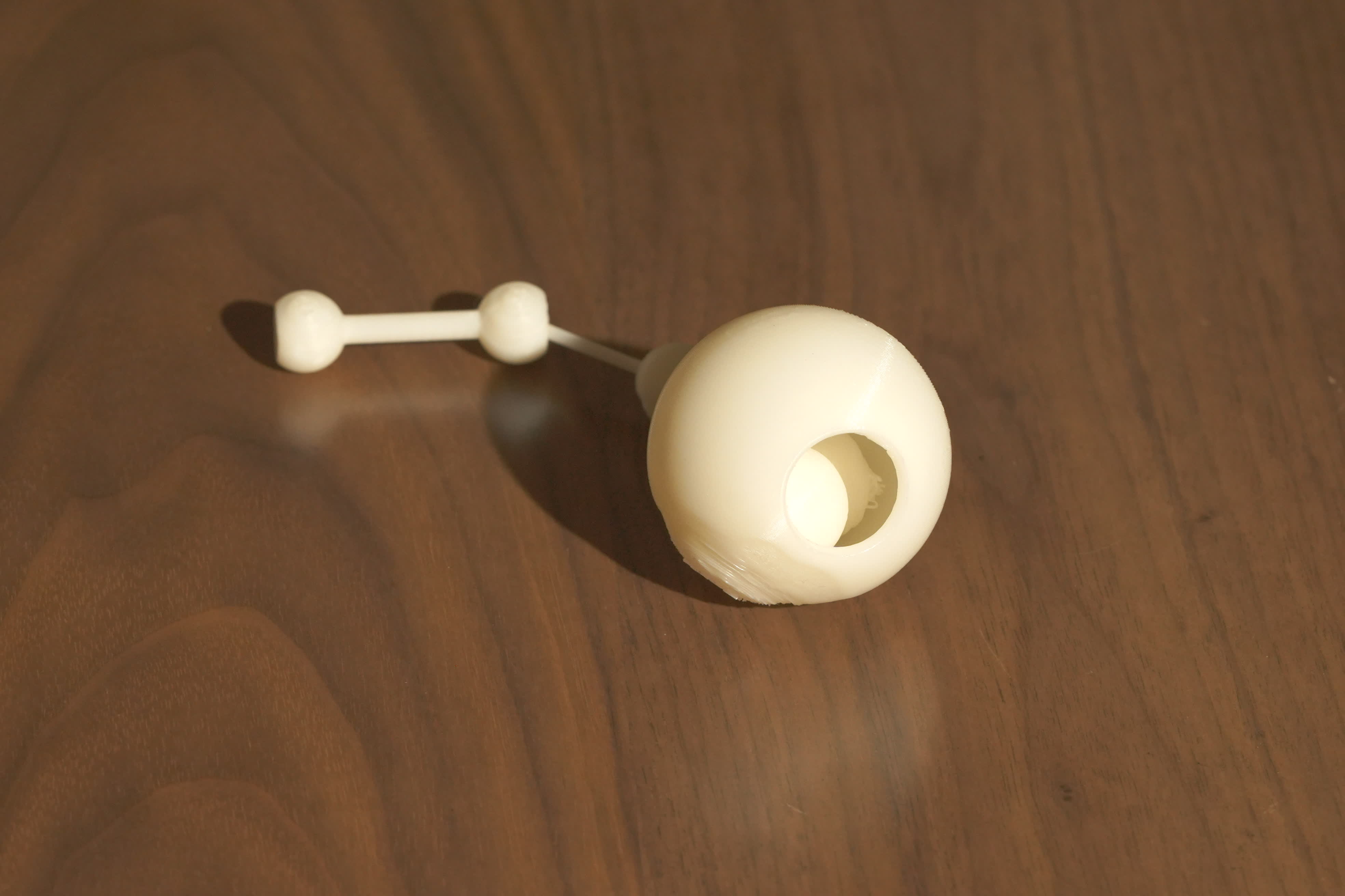
This involved 3D design and printing, as well as learning the advantages and limitations of doing so.
Make Something Big:
I made a bookcase bench for my daughter. It was a much needed, multi-purpose piece of furniture, and my daughter loves it.
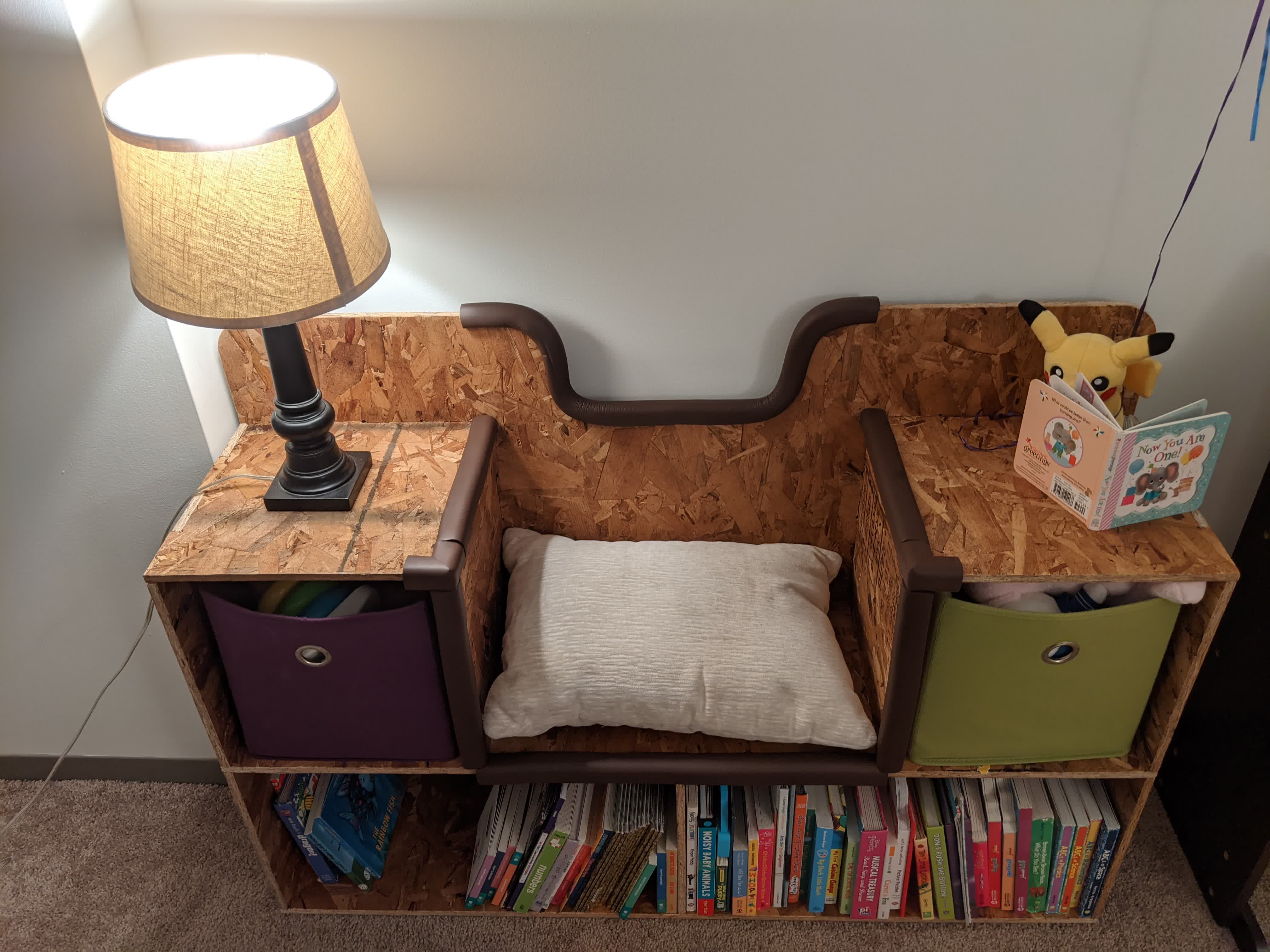
This mainly involved 3D design and 2D CNC milling.
Molding and Casting:
I made a shuriken. I've always wanted to be a ninja, so I'm a ninja now?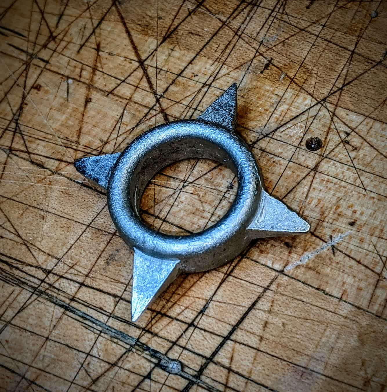
This involved 3D design, 3D CNC milling, and all the skills you need to mold and cast anything. This is a seriously underrated technique.
Electronics Production:
I built Clank, our very own PCB mill.
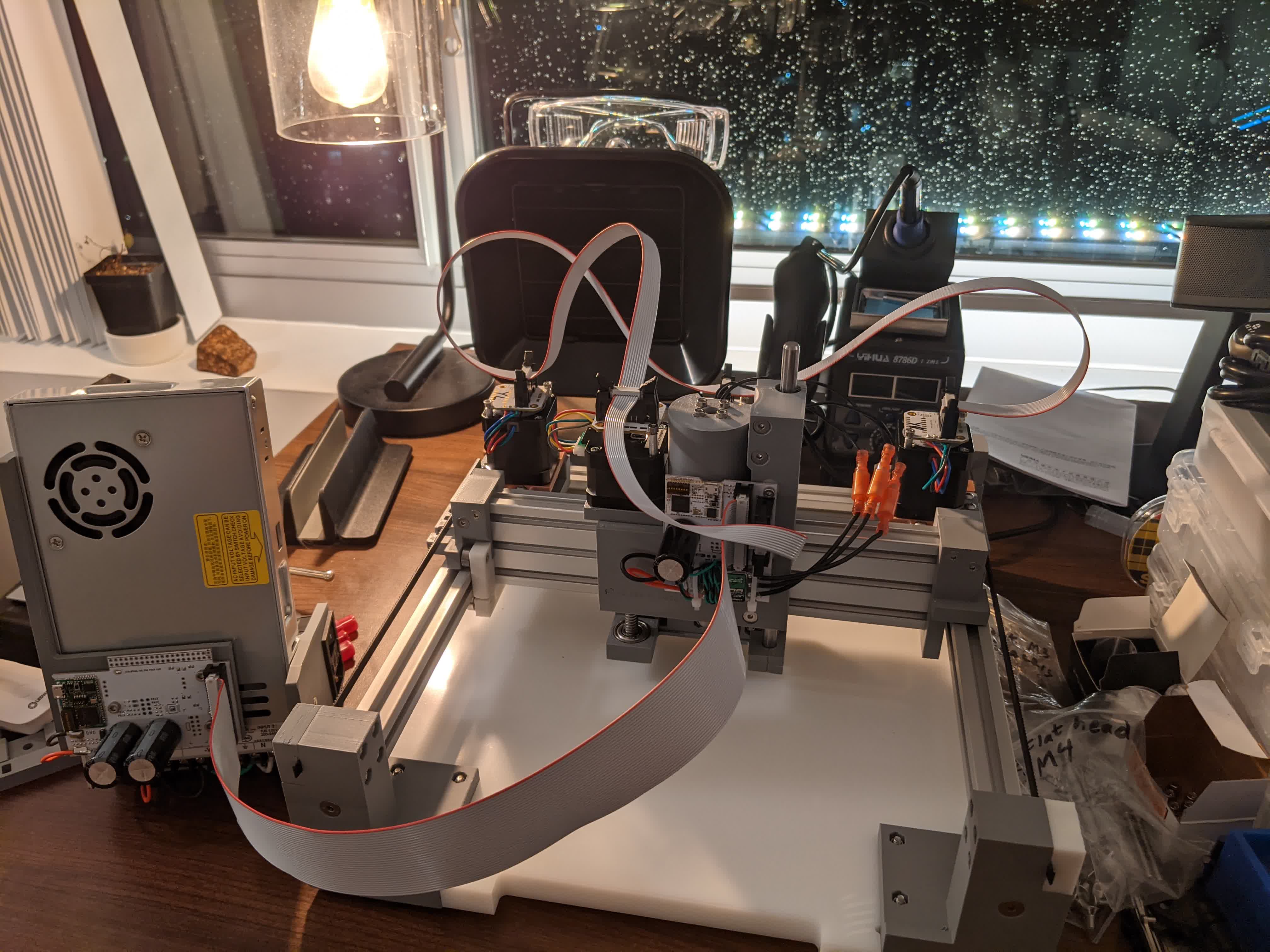
I then used it to make a predesigned programmer to program microprocessors.
This got us familiar with the PCB milling and soldering process. The objective of this week was to get comfortable with small scale CNC 2D milling and surface mount soldering.
Electronics Design:
I designed and made my own board with a button, an LED, and a microprocessor which controls both. I slowly began to understand how microprocessors work.
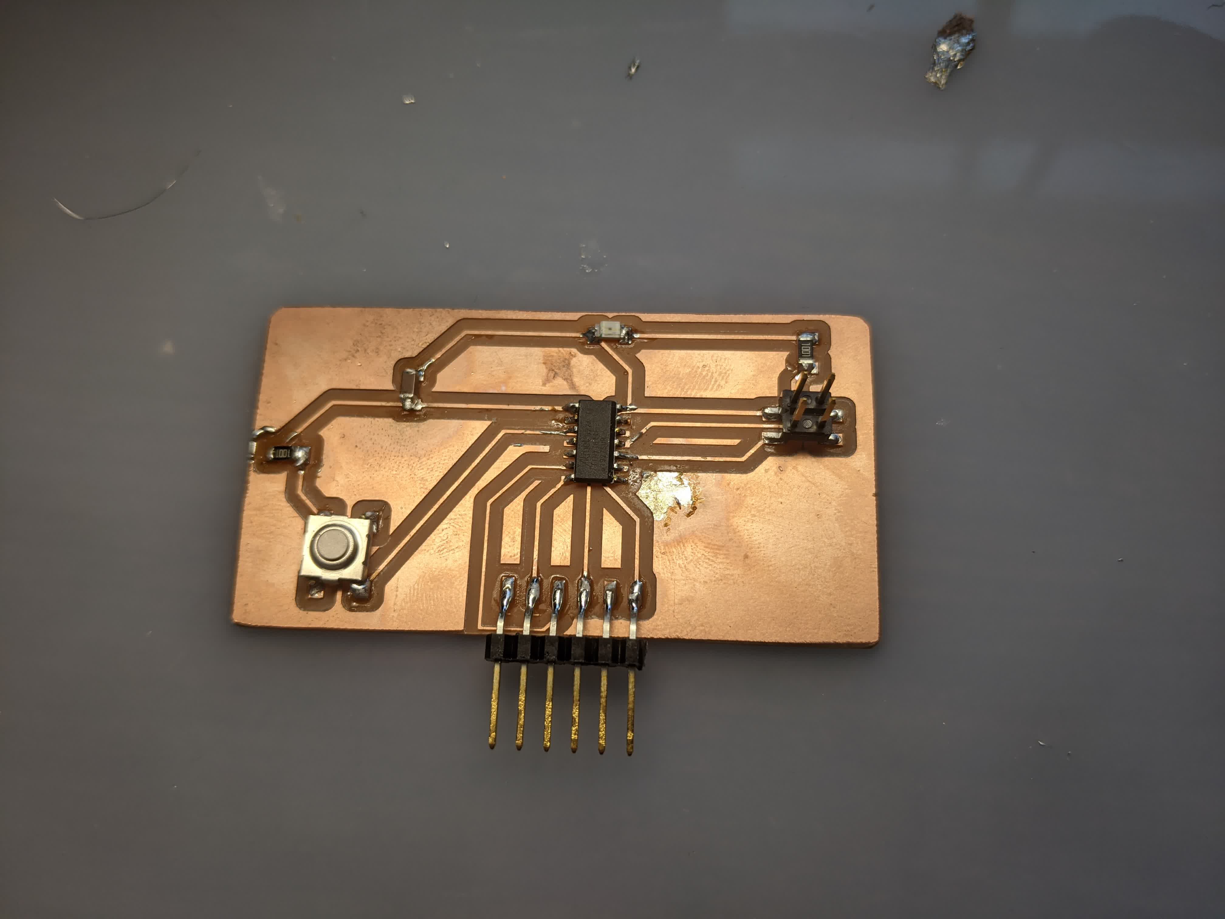
This involved learning how to designing a PCB from scratch (ie learning about all the elcronic devices you want to include like resistors and capacitors etc) and actually making it (milling and stuffing).
Embedded Programming:
I used the board that I designed during Electronics Production to program the LED to turn on when the button is pushed. To make things a bit more exciting, I then programmed it to make the LED blink fast when the button is pushed and slow when the button is not pushed.
This involved learning some C++ programming and more about the functions of the microprocessor pins.
Input Devices:
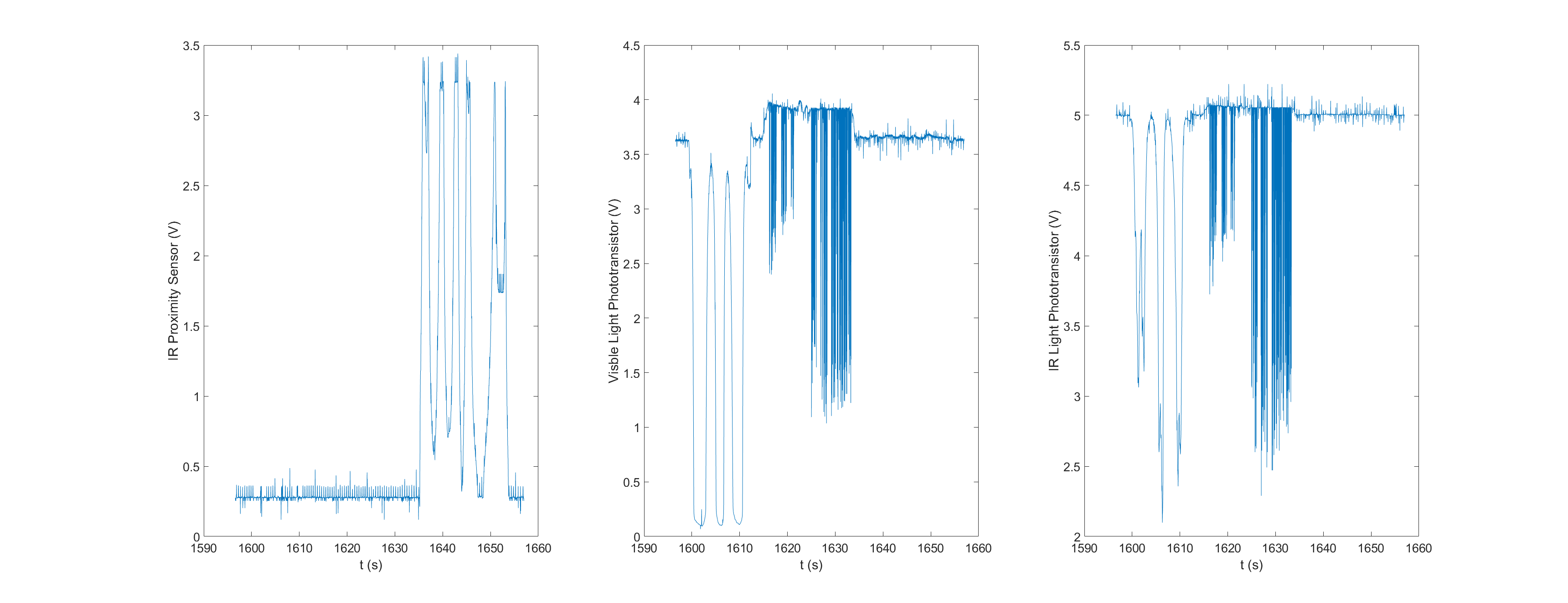
I made a board with a microprocessor communicating with visible light phototransistor, an IR phototransistor, and an IR proximity sensor.
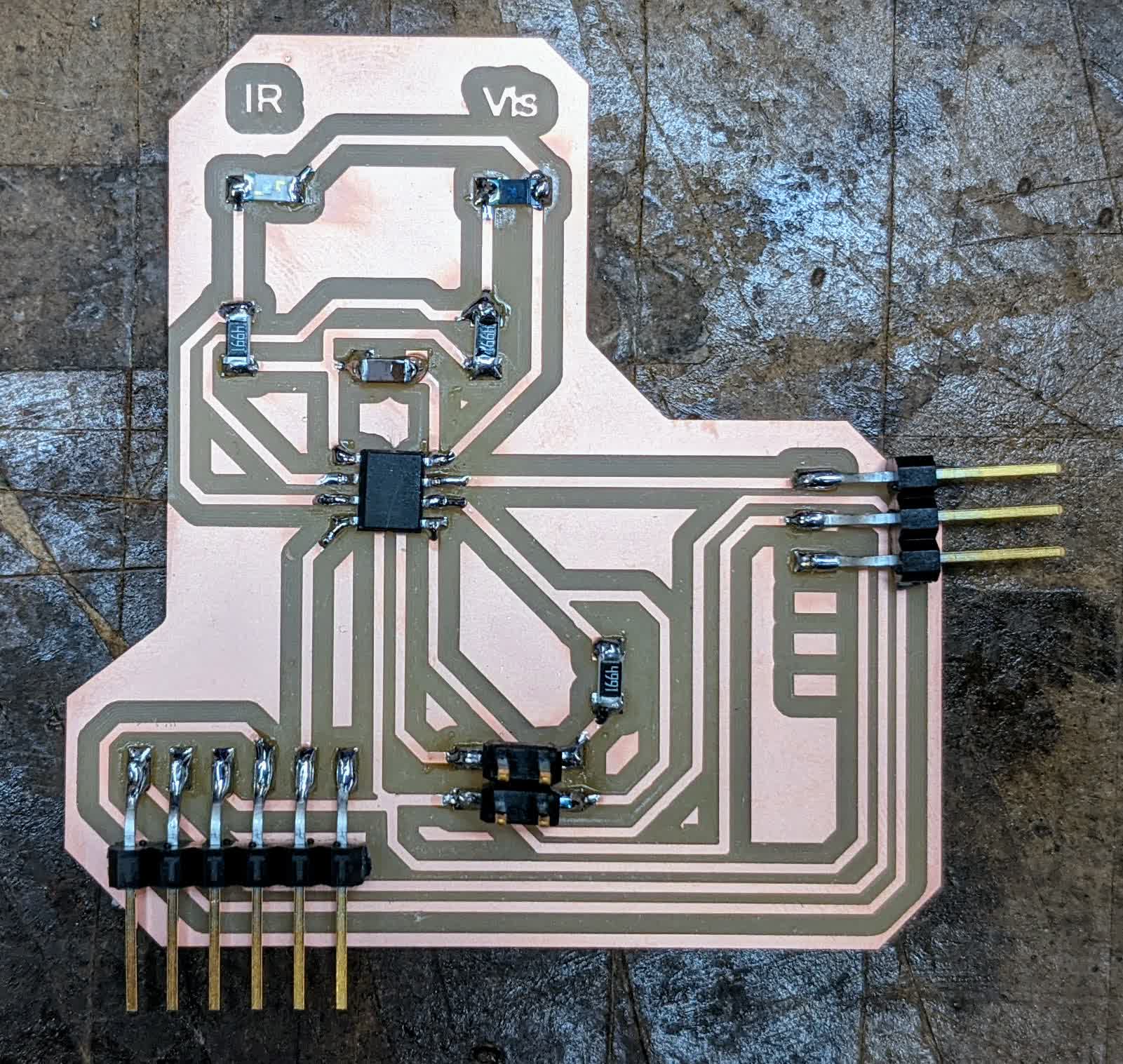
The phototransistors were programmed to pick up on light levels and the proximity sensor can detect distances up to 80cm. The IR detection was inspired by a cool DIY project I saw where someone used it to decode a TV remote's button frequencies to make your own remote. I did not do that, but I saw what the power and volume buttons' signals look like on my tv remote.
This involved designing and making my own PCB geared towards reading input devices. It was critical that I understand that not all the microprocessor pins are created equal, and the concept of pulsed width modulation for analog readings. I also learned how to log the data on my computer using Putty. In hindsight, I should have learned how to use the Serial monitor here.
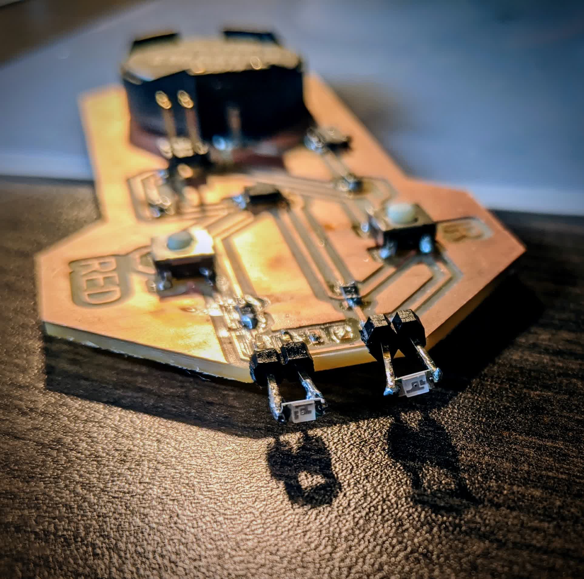
Output Devices:
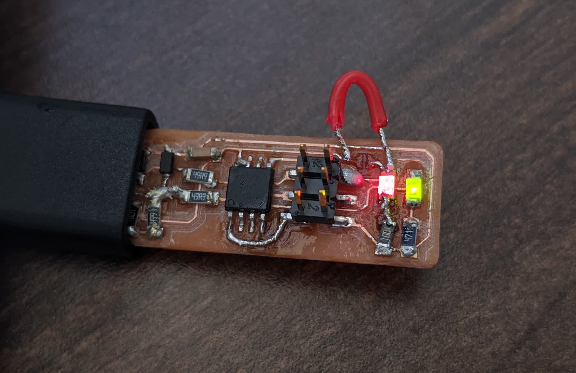
I made a light remote that can emit red light and IR light with the push of a button. I could have taken this a step further and made it emit IR light at the same frequency measured from my TV remote last week...but alas...time is the enemy.
This was one of the most exciting projects I did because I felt like I built something that did not have to be teathered to a computer. It has a battery, a switch, you can program it to emit signals that detectors can pick up on, and you can carry it in your pocket!
Here it is in action:
I also made a board that can control a motor based on how much light the phototransistor is picking up. Dark is slow and Light is fast. This was another moment I'll never forget. Seeing that motor respond like I wanted it to was beyond elating!
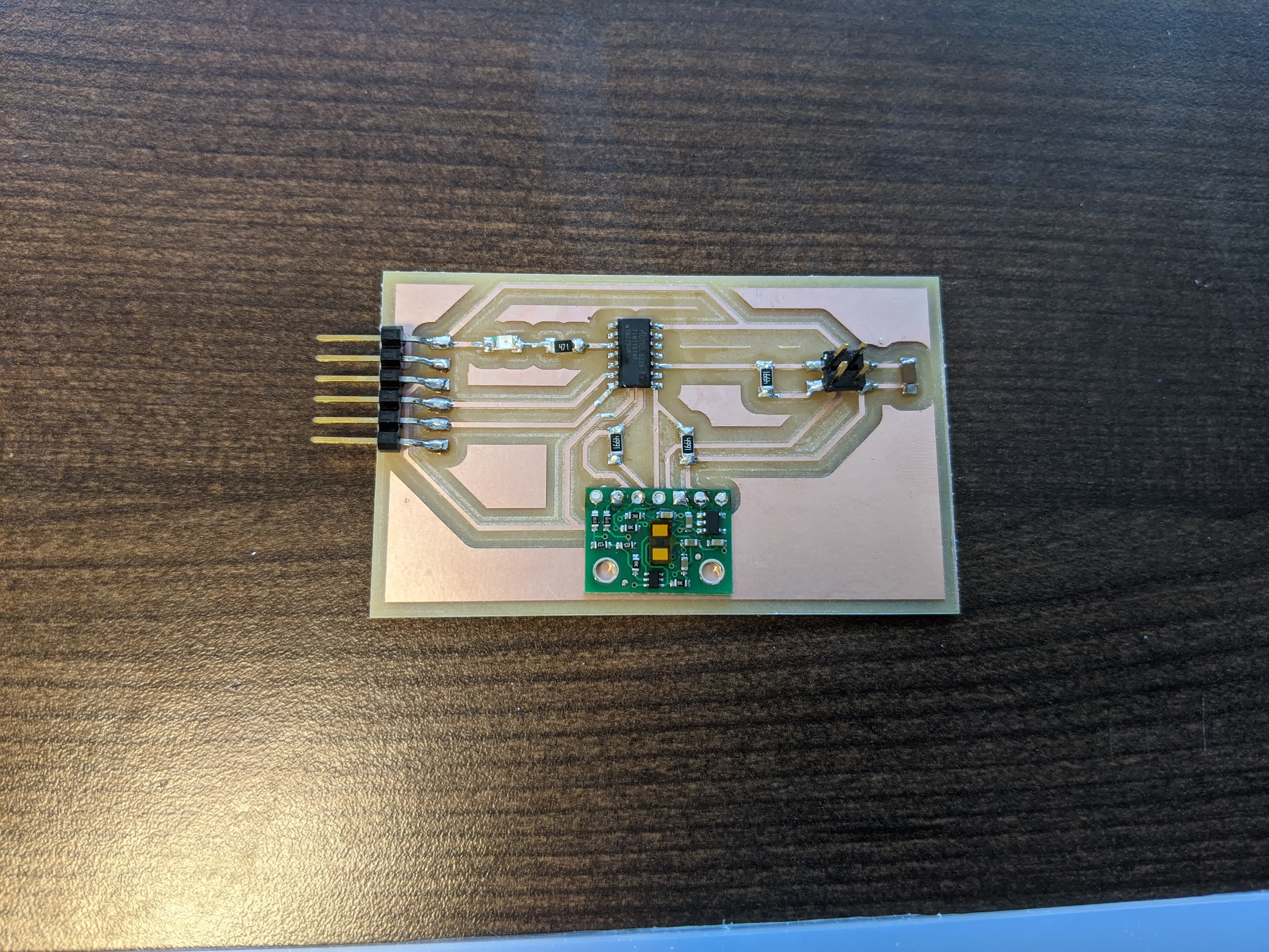
Finally, I made a board that can measure distances up to 4m using a time of flight lidar sensor which emits an IR laser and calculates the distance internally based on that. This was critical for my final project and my first experience dealing with I2C communication. This can arguably be viewed as an output device because it outputs distance. Note it took me 3 tries to get this right: first time i found out the microprocessor did not have enough memory for the program I was uploading, the second time I found out that for I2C devices, there are dedicated SDA (data) and SCL (clock) pins on the microprocessor. Third time's a charm! Yes, I designed, milled, stuffed 3 times and desoldered 2 times to make this!
This week involved designing and making multiple PCB's (we only needed one), and programming them to control an output device. This was the funnest week in my opinion. It is very cool to see things coming to life with an action!
Networking & Communications:
I made an Arduino like board (basically a microprocessor breakout board) with the ATtiny3216 which was made to control a motor. I have dubbed it the "Arduinalog"!
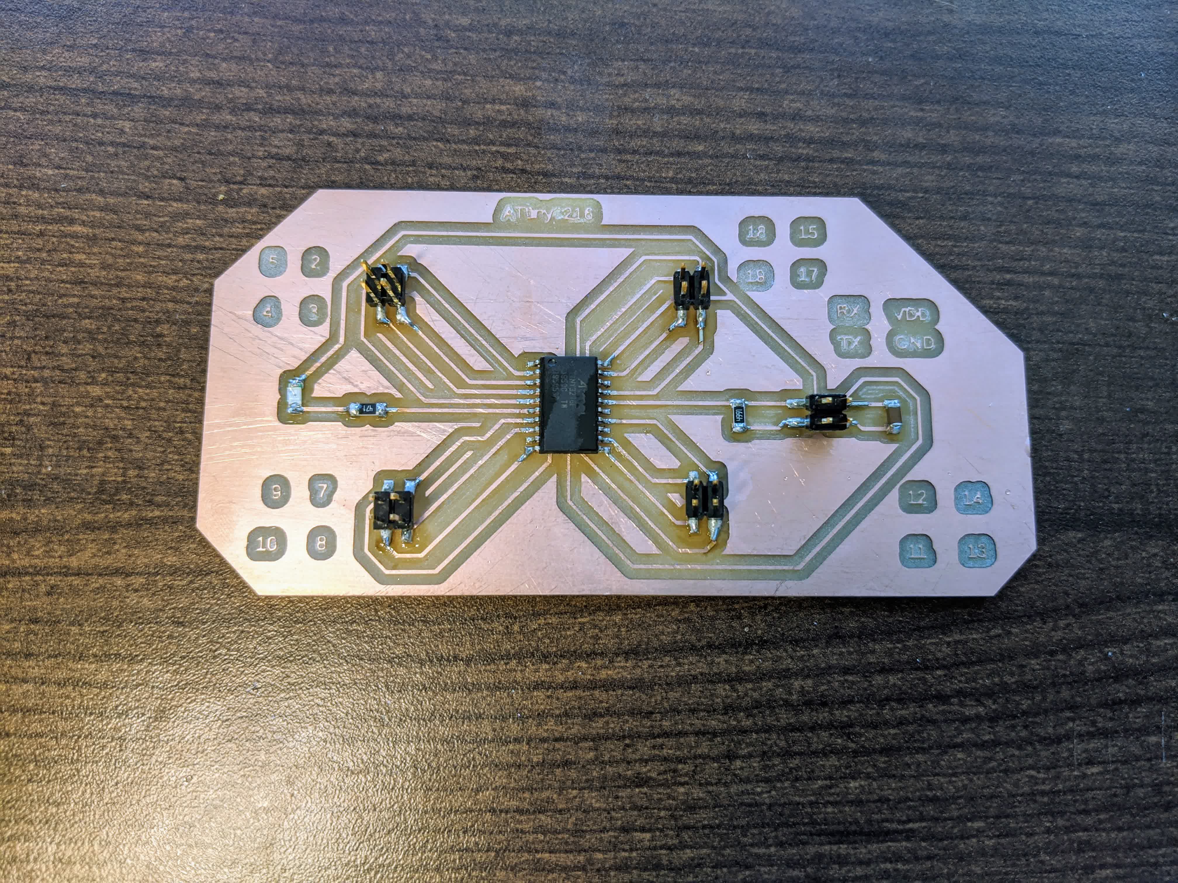
I used the time of flight board from Output Deivices ironically as an input device to communicate with the motor board and control the motors based on the distance measurements as feedback.
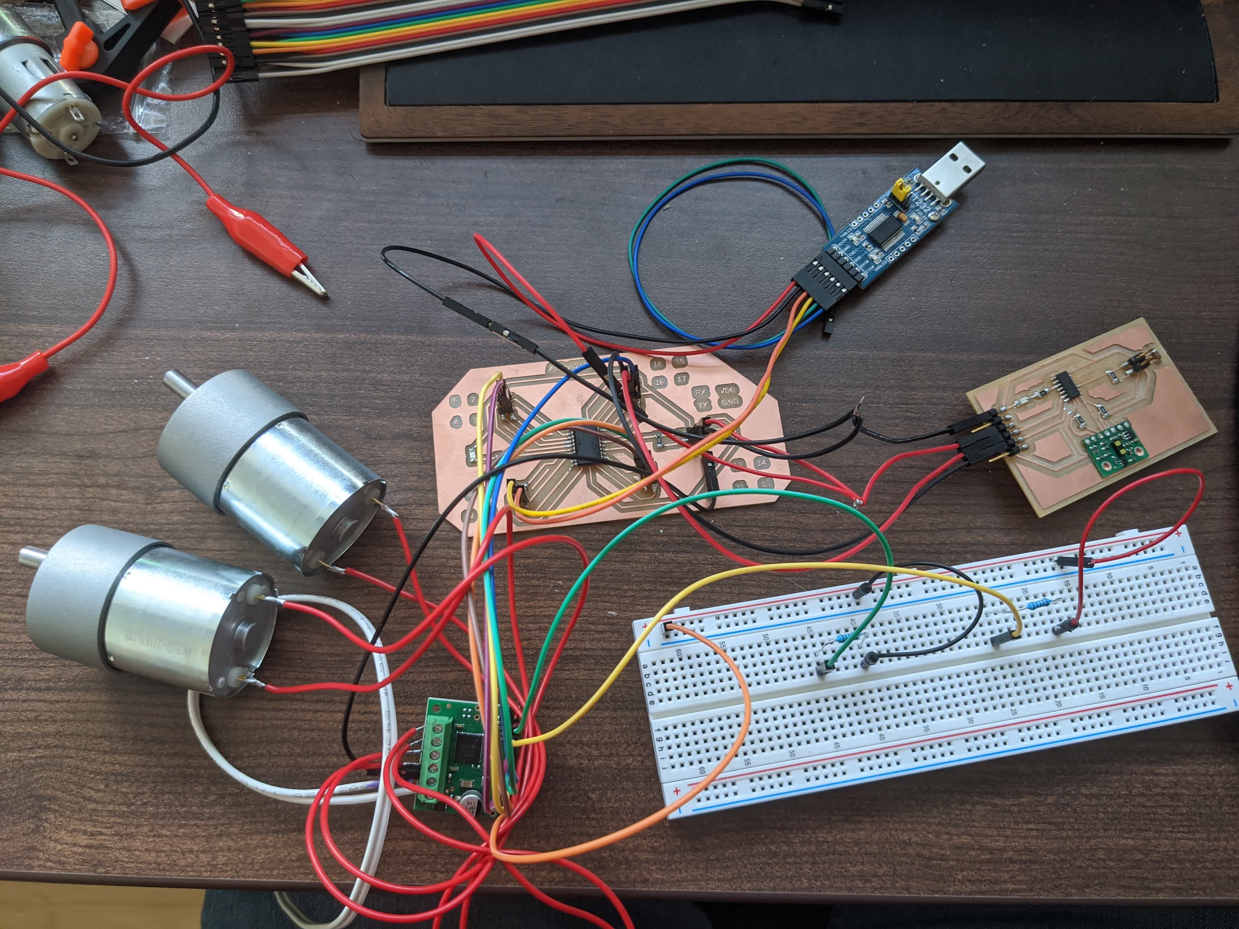
Here it is in action:
This week involved learning how to get 2 boards talking to one another. The time of flight board is using I2C communication, but to get it to talk to the motor control board I used serial communication. In hindsight, I wish I had gone with bluetooth to better fit my final project physically, but there's always time in the future.
Interface and Application Programming:
I made an application dedicated to the time of flight sesnor. It graphically displays the distance measurement, peak signal, and the ambient light signal, where 3 circles representing each measurement grow and shrink based on the measurements.
This was important to understand the capabilities and sensitivites of the sensor like how does it perform in the day vs at night or how quick it can report a change in measurement.
This week involved learning Processing and some Java, though it did not have to. There were many options.
Contact