
Computer-Controlled Cutting
"Numeric control (also computer numeric control, abbreviated CNC) is the automated control of machining tools (such as drills, lathes, mills, grinders, routers and 3D printers) by means of a computer." -Wikipedia
Group Assignment
1. This week started off with learning how to use the laser cutter in the architecture shop.
I met with my group, Suwan Kim and Se Hwan Jeon, in the Architecture shop to work through using the laser cutter. As an MArch student, Suwan had experience using the shop's laser cutter before, so she showed us how to open the Rhino software and draw test squares to cut (Fig. 1A). It is best to dedicate a section in the corner of your material to do these test cuts, especially if you are using a new material for the first time and trying to figure out the appropriate settings to use.

Fig. 1A. Created test squares in Rhino to laser cut.
The material we were using was corrugated cardboard (3/16" thick), which could be flammable—like anything else in the laser cutter—so we were cautious while testing different settings. With the suggestion of a Shop Monitor roaming the area, we varied speed and power settings while keeping frequency and other settings constant (Fig. 1B). We mapped these settings to different colors which we could link to our different test squares. This would allow us to test multiple settings in one run of the laser cutter.

Fig. 1B. Tested different speed and power settings.
We started off trying to cut our test squares on the 60W laser cutter (Fig. 1C). However, all of our attempts at cutting through the cardboard at different settings failed, even after modifying the speed, power, and frequency (Fig. 1D). We needed to find a new solution, and so we decided to move to the more powerful 120W laser cutter on the other side of the room.

Fig. 1C. Attempted to cut with the 60W machine.

Fig. 1D. Repeated the steps in Fig. 1-Fig. 3 multiple times but could not make a successful cut.
The 120W laser cutter worked a lot better for us, given the 60W machine did not seem like it produced enough power to cut through the cardboard. We tested multiple settings using the test square method again, and ultimately found the combination of speed, power, and frequency that allowed us to cut through the cardboard reproducibly (Fig. 1E). We were happy!
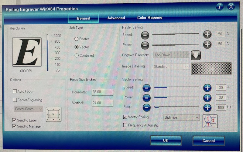
Fig. 1E. Determined settings for 120W machine to cut.
Using calipers, we measured the width of a 1" square we laser cut (Fig. 1F). The value of 0.99" indicated that the kerf of the 120W laser cutter was 0.01", meaning when designing parts to laser cut, we should extend our lines by half of this value (0.005") to account for the material that will be removed by the laser. We should note that there is probably a more precise way to measure the kerf, as the calipers we used only measured to two decimal places.
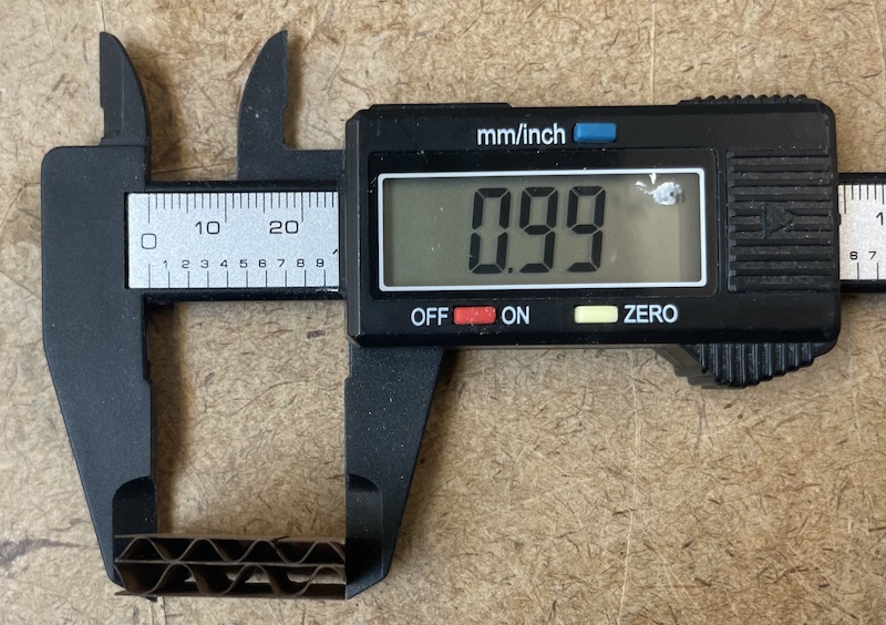
Fig. 1F. Measured the laser cut part to determine the kerf.
Overall, after this exercise our group felt confident that we could design and cut objects using the laser cutter in the Architecture shop.
2. Our group also learned how to use the vinyl cutter.
I had never used—or frankly ever heard of—a vinyl cutter before, and given the praise about the machine from Prof. Gershenfeld in class, I was excited to learn how to use it. The process of using the vinyl cutter was relatively straightforward, as all of the steps were laid out on the Architecture Shop site. While going through the documentation, we learned there was a "Test" button on the machine that you could press to automatically start a preloaded program to cut a square inscribed in a circle (Fig. 2A).

Fig 2A. Ran the test print directly from the vinyl cutter.
The next step was to "weed" off the stickers that were just vinyl cut, which was actually quite a fun process (Fig. 2B)! These shapes were particularly easy to weed, but I could definitely see how more intricate shapes could take time and skill to weed off without accidentally tearing or otherwise ruining the sticker. I suppose we can leave that as a challenge for a future week.

Fig. 2B. Successfully weeded off the test print.
Following cutting and weeding the test print, we proceeded in the documentation and learned how to upload and image into the vinyl cutter program in order to prepare the machine for cutting (Fig. 2C). This required needing to use Terminal and entering a few lines of code that were specified in the documentation. We selected an image that was stored on the computer for uploading into the program, and then started the machine to make the cut (Fig. 2D).

Fig. 2C. Followed the online instructions to use the vinyl cutter.

Fig. 2D. Made a successful cut.
The cutting process was relatively fast, and following the weeding process, we were left with our masterpiece (Fig. 2E).

Fig. 2E. It's a cat!
The cat has found a new home on Suwan's water bottle, and serves as a reminder of our successful training on the Architecture Shop vinyl cutter.
Individual Assignment
3. To test my skills I designed and laser cut a Trammel of Archimedes.
I wanted to make some sort of kinetic sculpture for my project this week, and I remembered the "Trammel of Archimedes" (also known as a "Kentucky do-nothing machine"), a mechanism I built out of LEGO when I was younger. I found a picture of the mechanism on the web (Fig. 3A). I challenged myself to design and construct the mechanism out of laser cut cardboard.

Fig. 3A. Discovered a cool mechanism (Google Images).
I had experience using CAD software (Autodesk Fusion 360 and SolidWorks) before, but I had never used the "parameter" function. Selecting Autodesk Fusion 360 for the project, I learned how to use and implemented parameterization to make the design scalable (Fig. 3B). Since these parts I designed were very large, I did not modify them to account for the kerf of the laser, as I anticipated the kerf would have negligible effect on the assembly; however, if I were to have designed the parts smaller, I would have accounted for the kerf. I learned a lot in this process of making a parametric design, and I will surely incorporate the parameter function in future projects as well.

Fig. 3B. Made parametric design in Autodesk Fusion 360.
The Group Assignment on the laser cutter was extremely helpful in preparing me for setting up the design to be cut. After exporting the design from Autodesk Fusion 360 as a .dwg file, I uploaded it into the Rhino software on the computer connected to the 120W laser cutter. I then selected all the lines I wanted to be cut and applied the settings I had determined in Fig. 1E. Following this setup, I started the print on the laser cutter (Fig. 3C).

Fig. 3C. Laser cut with 120W machine
The parts cut perfectly, and removed easily from the base carboard material. The assembly process was also relatively straightforward, given I had previously built a mechanism like this and knew how all of the parts fit together. I took a series of photos to document the functionality of the mechanism (Fig. 3D). It worked! In a future iteration, I would make the design a lot cleaner, with tighter tolerances, curved edges, and a spinning handle so that it could be operated with one hand. I had no use for the mechanism at home as it was quite large, so I decided to disassemble and recycle it (Fig. 3E).

Fig. 3D. Mechanism in action.

Fig. 3E. Recycling in action.
Designing, laser cutting, and assembling a Trammel of Archimedes was a fun project that solidified my skills, but I wanted something to take home and display proudly—so I decided to do another project.
4. The culmination of my skills this week led to the creation of a novel tensegrity structure fabricated by a single repeating unit.
Building the Trammel of Archimedes reminded me of another interesting mechanism I previously made out of LEGO—a "tensegrity" structure. This is a contstruction utilizing tension and compression to create a seemingly floating appearance Fig. 4A. I thought this would be a worthy challenge to take on for the rest of the time I had this week.

Fig. 4A. Discovered a cool structure (Google Images).
Looking at images on the web, I noticed that many of the tensegrity structures people have built involve several unique pieces that are assembled together. At minimum, there is a pair of two unique pieces, a base and an extending bar, that are connected with a wire. A twist I wanted to take on the tensegrity structure was to design one involving only a single unique piece. In this way, the piece can join with itself to create the base, and also serve as the extending bar. I had not seen a design like this so I turned to my iPad and sketched out my thoughts (Fig. 4B). In this evolution of my thought process, you can see the convergence on a repeating unit that would serve as a single part that can assemble the whole structure.

Fig. 4B. Designed single simple shape.
After sketching the simple shape, I recreated the design in CAD software (Fig. 4C). I used paramaterization to make the design scaleable, and made the dimensions small (each unit is roughly 6" in length) in order to have an assembled structure that can be displayed in my room. The CAD file can be downloaded here.

Fig. 4C. Made a parametric design in Autodesk Fusion 360.
In the process of designing the structure and making refinements, I decided to print the structure on paper and try to assemble it "arts-and-crafts" style (Fig. 4D). This turned out to be useful in deciding what the length of each unit should be.

Fig. 4D. Printed on paper to test it out.
When I was confident the design could be assembled as I imagined, I sent the print to the laser cutter (Fig. 4E). Again, the settings selected for the cardboard cutting allowed for it to be cut and removed perfectly. I was left with many copies of a single piece, that I then assembled together. In a future iteration, I might want to refine the design of the press-fit joints to chamfered or other similar types of joints.

Fig. 4E. Laser cut with 120W machine.
The assembly took around 30 minutes, as it was difficult to hold the pieces in place while tying metal wire to them. Nevertheless, I managed to assemble the tensegrity structure and I am happy with how it turned out (Fig. 4F). The structure floats as it should (given a little finangling with the wire). The one feature I did not forsee was that the structure has to sit at the edge of the table to allow the extension that extrudes out of the bottom to clear the floor on which the structure sits. This is actually a neat feature as it adds to the "floating" nature of the structure!
Fig. 4F. Assembled structure.
In hindsight, I built two structures I previously built from LEGO, so it may have been better to just laser cut and assemble custom LEGO bricks, then construct these and other structures as well! Nevertheless, I enjoyed the assignments this week and learned a lot about laser cutting and vinyl cutting.