Input Devices
"In computing, an input device is a piece of equipment used to provide data and control signals to an information processing system, such as a computer or information appliance." -Wikipedia
Group Assignment
1. With my group I probed an input device's analog levels and digital signals.
Fellow architecture section student and class TA Niklas Hagemann created a capacitive sensor and used the oscilloscope's trigger function to take a snapshot of the discharge of the capacitor (Fig. 1A). Niklas kindly shared his results with the rest of the class.

Fig. 1A. Capacitive sensor readout on oscilloscope.
I will likely be doing a lot more signal processing in the next several weeks, so this was a good introduction!
Individual Assignment
2. I tested the buttons on the microcontroller board I designed and further developed the circuit for my final project.
In Week 06 I created a circuit board that simulated the functionality of my Final Project. This week, I tested the input components of the circuit board: the buttons. In preparation for this, and in order to help write the code to connect the buttons to the desired LED flashing, I created a simplified circuit with a single button and single LED (Fig. 2A).
Fig. 2A. Testing a single button and single LED circuit.
Following the creation of the simple circuit, I expanded it to include a total of 3 buttons and 4 LEDs (Fig. 2B). Here, I made each button correspond to a different sequence of LEDs flashing. This will mimic my final circuit where instead of LEDs I have DC motors so each button will start a different sequence of motor operations.
Fig. 2B. Testing a three button and four LED circuit.
The three button and four LED circuit is the PCB I made previously. I then wrote a Arduino script to test the function of the buttons and LEDs on my soldered PCB. It was a simple program: when the top button is pressed, LEDs 1 & 3 turn on; when the middle button is pressed, LEDs 2 & 4 turn on; and when the bottom button is pressed, all LEDs turn on (Fig. 2C).

Fig. 2C. Arduino code for testing each components.
I uploaded the code to the board and tested it, but was dissapointed to see it not work. I thought the metal casing on the buttons might have been interfering with the circut, so I removed these and tried again. This time, it worked (Fig. 2D). The soldered PCB was a little finicky, for example, I would have to hold it in a specific way in order to have the buttons work. I think with better soldering of the components it would have performed better. However, for the first board I designed, milled, and soldered from scratch, I was happy with it!
Fig. 2D. Testing the buttons and the LEDs of the soldered PCB.
Expanding the functionality of the circuit, I added a OLED display to indicate which program is running, i.e. which button had been pressed (Fig. 2E). This will be useful for a user to visually know which motors are running in the final design.
Fig. 2E. Added an OLED display to the circuit.
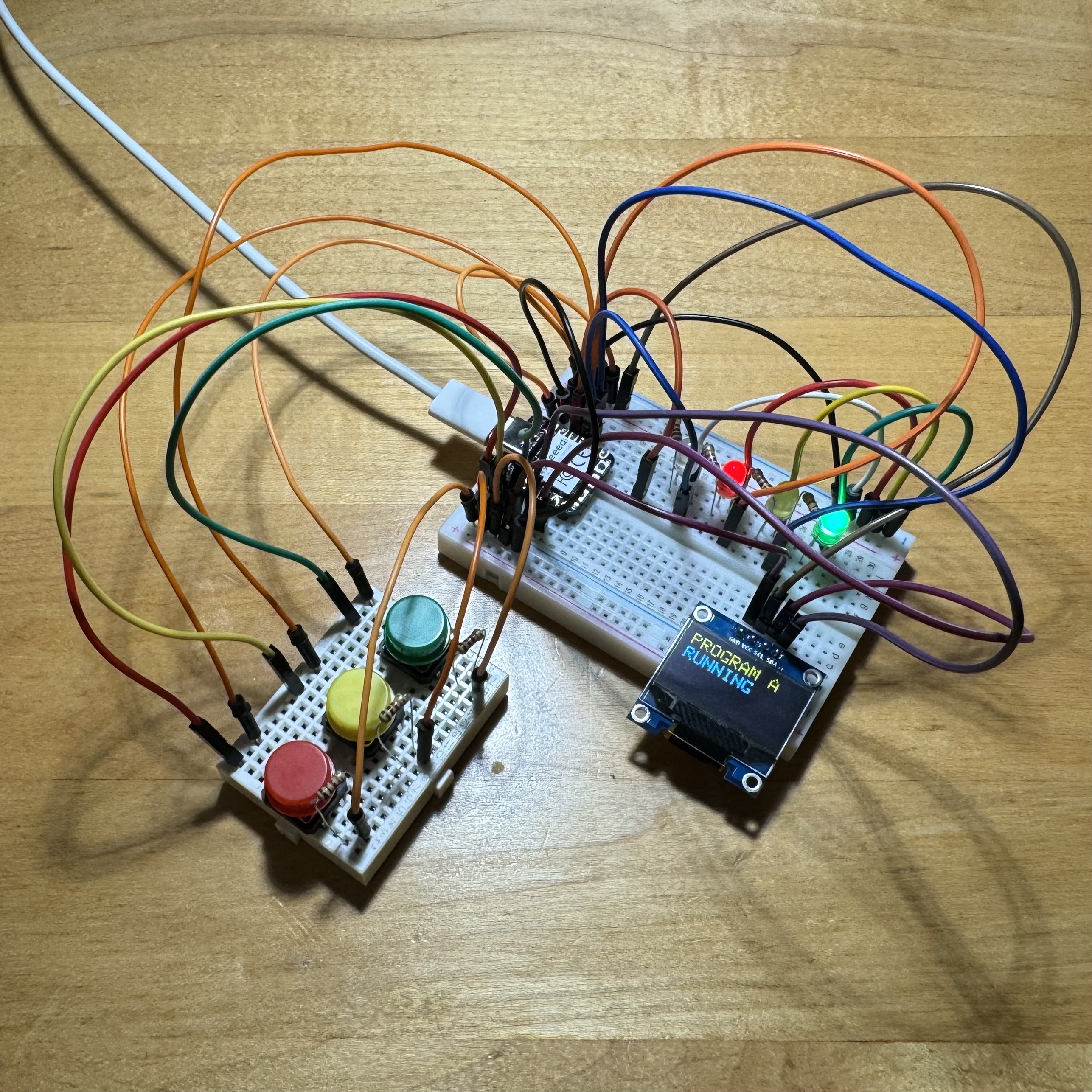
My final update to the circuit was to have repeating sequences of LED flashes play with each button press, instead of just a single flash of LEDs (Fig. 2F). This sets the stage for swapping out the LEDs with motors in a future week so that I can get the final circuit working without worrying about writing new code. The .ino Arduino code for this circuit can be downloaded here.
Fig. 2F. Simulating the final circuit with buttons, an OLED display, and LEDs.
In conclusion, I made a lot of progress this week toward the design of my circuit for my final project. I was also happy to see my first PCB work, though I did note there are some changes I would make in a future PCB design. Luckily, I will have many more opportunities to make a test PCBs, including next week, where I hope to test the output devices (i.e. DC motors) that will be included in my final circuit!