Embedded Programming
"An embedded system is a computer system—a combination of a computer processor, computer memory, and input/output peripheral devices—that has a dedicated function within a larger mechanical or electronic system." -Wikipedia
Individual Assignment
1. This week I learned how to use the Seeed XIAO RP2040 microcontroller board, and programmed it to communicate in Morse code.
I have had experience working with Raspberry Pi microcontrollers previously, but had never used the Seeed XIAO RP2040 before. It was therefore quite helpful to look up the data sheet for this board, read documentation and tutorials on it, and learn what it can do (Fig. 1A).

Fig. 1A. Browsed the data sheet for the microcontroller
I had experience with using the Arduino IDE before, so I loaded it up and connected my board using the USB-C connection. As suggested in class, I uploaded the Arduino IDE "Blink" example code to the board (Fig. 1B). At first I did not think it uploaded correctly, as I was expecting the RGB light to be blinking, but I quickly realized there are actually two LEDs on the board! There is not only the "RGB LED," but also the "USER LED," which was the one that was blinking. It was great that it was working, but I wanted to modify the code to have the RGB LED blink. I decided to make this my project.

Fig. 1B. Downloaded the Arduino IDE and connected the microcontroller to run the "Blink" example code.
My idea was to have the RGB LED blink, but in a controlled way as a form of communication. The idea came to me to use Morse code to serve as the mode of communication, by tuning the duration of the flashes of light. I found an online "Morse Code Translator" in which I could enter a message and receive the coded output (Fig. 1C).

Fig. 1C. Converted "HTMAA" to Morse code.
As Morse code consists of "dots," "dashes," and "spaces," the next step was to decide how long each of these features would last. This was accomplished through trial and error in entering values for the time delays and then uploading and watching the board (Fig. 1D). In early attempts the flashes of light were too fast so I could not discern the difference between a dot and a dash, or tell when there was supposed to be a space. Ultimately, I figured out the optimal speed of flashes to discern the message. The code can be downloaded here.

Fig. 1D. Implemented the secret message into code.
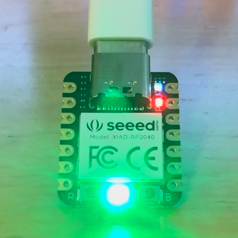
I made the message appear with blue flashes and repeat on an infinite loop (Fig. 1E). Additionally, I coded a green flash between each loop to indicate the end of the message. Initially, I had a red light as the background, turned on when LED is neither blue nor green. However, this made interpreting the flashes difficult as the red light looked like a separate flash, and therefore, it was not possible to discern whether the message was coded by the blue flashes or the red flashes. In the end, though, the message was successfully coded!
Fig. 1E. Blue flashes are dots and dashes while a green flash signals end of message.
In the future, it would be cool to make a system that could display multiple messages in different colors, for example one in blue and one in red, as long as the messages do not overlap (or if they do, use a combination of the colors like purple) for shared flashes.
Group Assignment
2. With my group, I compared the Ardunio IDE "Blink" example running on the RP2040 to an equivalent MicroPython code running on a virtual microcontroller.
I worked with Suwan Kim to create the "Blink" code in a different environment than the Arduino IDE. We were both individually using the Seeed XIAO RP2040, so we had to find a different microcontroller to use. We found a cool online environment that runs a virtual microcontroller with MicroPython code input, all embedded on a single webpage (Fig. 2A). Using this, we coded the "Blink" example and ran it on the virtual microcontroller.
Fig. 2A. We wrote the code to be exactly the same as the Arduino IDE example.
I was fascinated by this online microcontroller and might return to it to test out ideas, since the process of writing code, uploading it to the board, and visualizing the output is faster than doing the same thing with a physical board. Regardless, I am looking forward to applying these embedded programming skills to a physical circuit in future weeks!