My final project is the gut machine.
1. Introduction
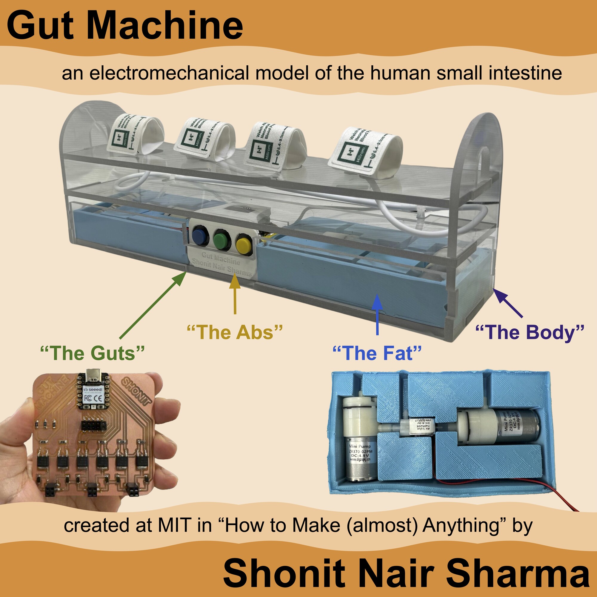
I made a “gut machine,” a true-to-size, electromechanical replica of the human small intestine that can be programmed to push and squeeze ingested matter. In Week 01, I created a sketch of the gut machine (Fig. 1A). With the gut machine, we can observe how motility impacts drug delivery from pills, which will help us develop novel ingestible devices that can withstand or harness the dynamic gut environment.
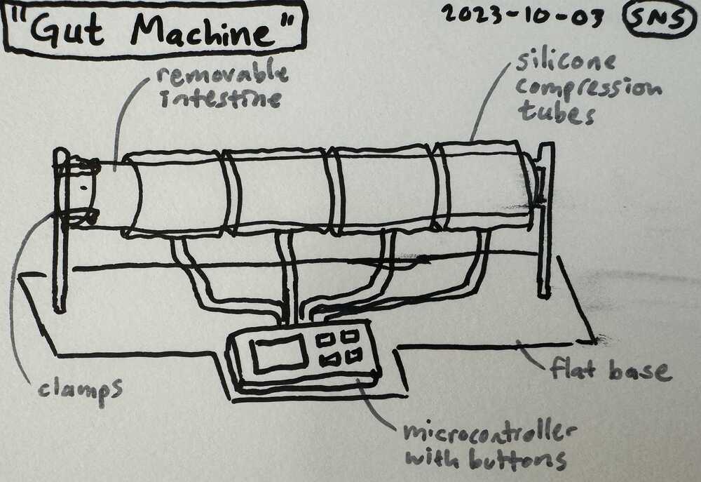
Fig. 1A. Sketch of the gut machine.
In Week 02, I created a computer-aided design render of my sketch (Fig. 1B).
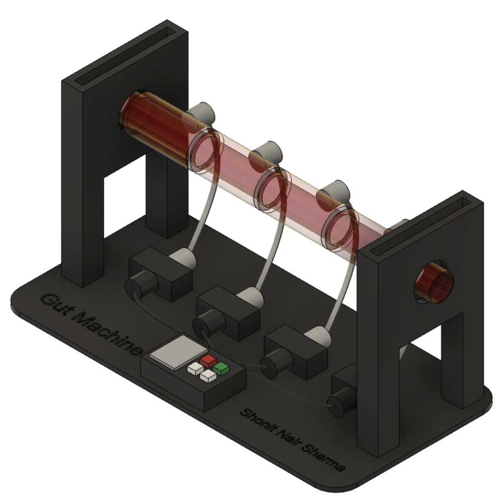
Fig. 1B. Render of the gut machine.
I also created a CAD mockup of a device component which could be tested in the gut machine (Fig. 1C).
Fig. 1C. Component of an engineered robotic pill.
Prototyping the gut machine involved skills learned and practiced in all previous weeks of the class. The design and execution of creating the gut machine occured in four steps (Fig. 1D).
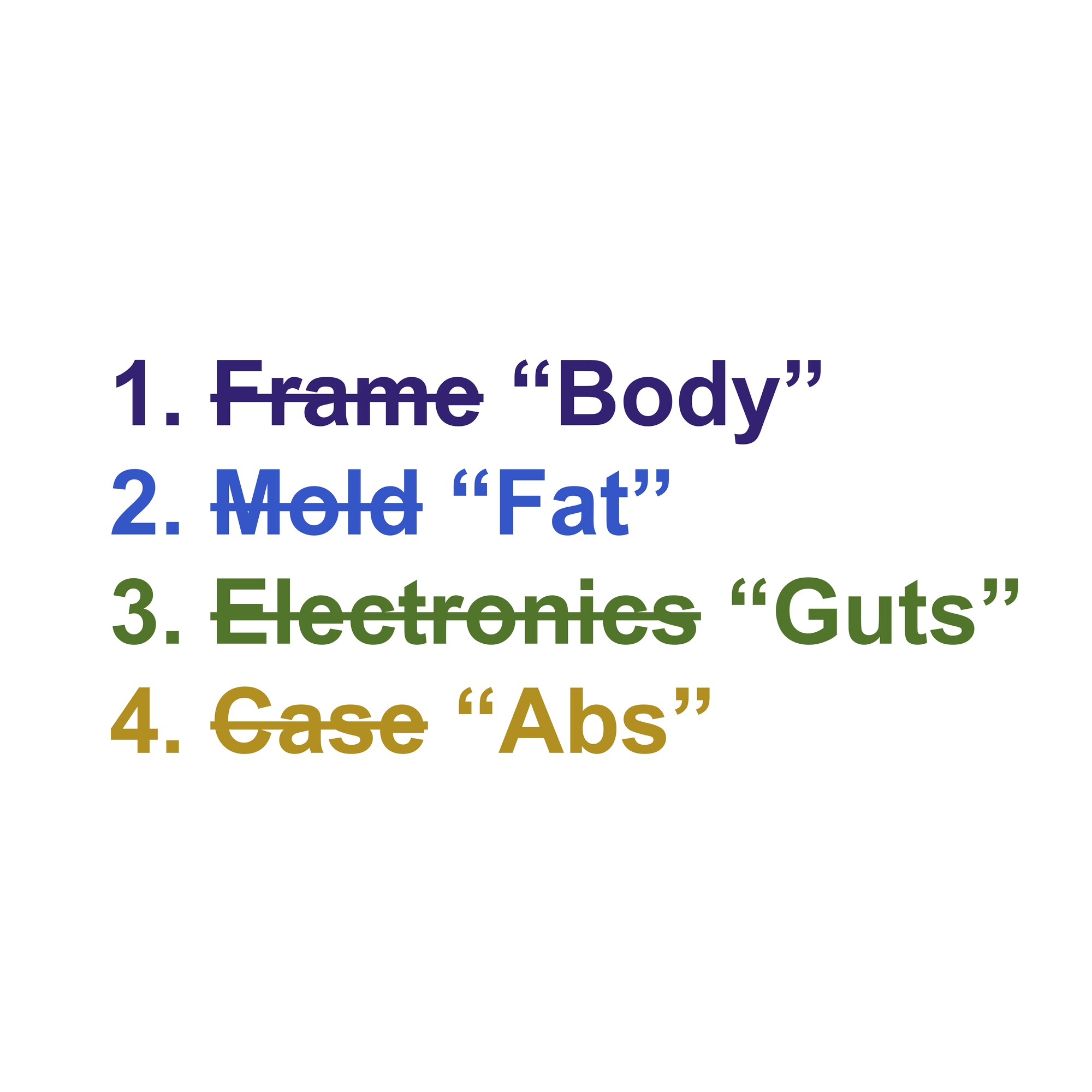
Fig. 1D. Steps for creating the gut machine.
The Frame provides the "Body" of the gut machine, giving a structure in which all components have a home. The Mold is the "Fat" of the gut machine, acting as a shock-absorber for vibrations created by the motors as they run. The Electronics are the "Guts" of the gut machine, allowing the contractions to actually happen. The Case is the "Abs" of the gut machine, providing a protective barrier for the sensitive insides while being aesthetically-pleasing to look at. This page will document each of these steps in detail.
2. The Body
Making the frame involved Computer-Aided Design, Computer-Controlled Cutting, and Water Jet Cutting skills. A large part of my process for this project, or any project in general, is sketching out the idea. Starting with a sketch that included dimensions of the gut machine, I turned this into a CAD drawing in Fusion 360, and ultimatley an assembly that I rendered (Fig. 2A).
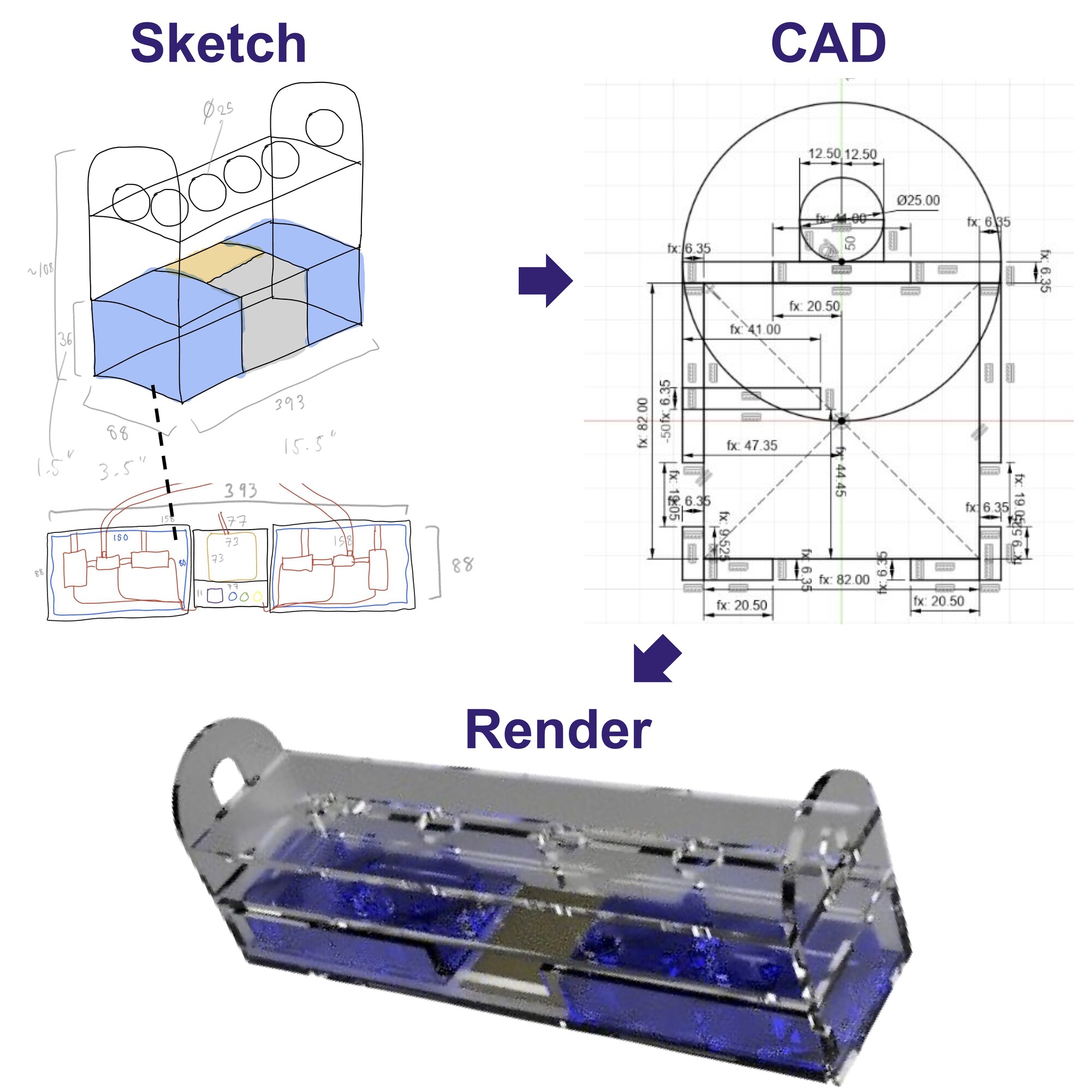
Fig. 2A. Creating a render.
As described in Week 14, I used the OMAX water jet cutter in the Architecture Shop to cut polycarbonate sheets into peices that could be assembled into the frame (Fig. 2B).. The .dxf file can be downloaded here.
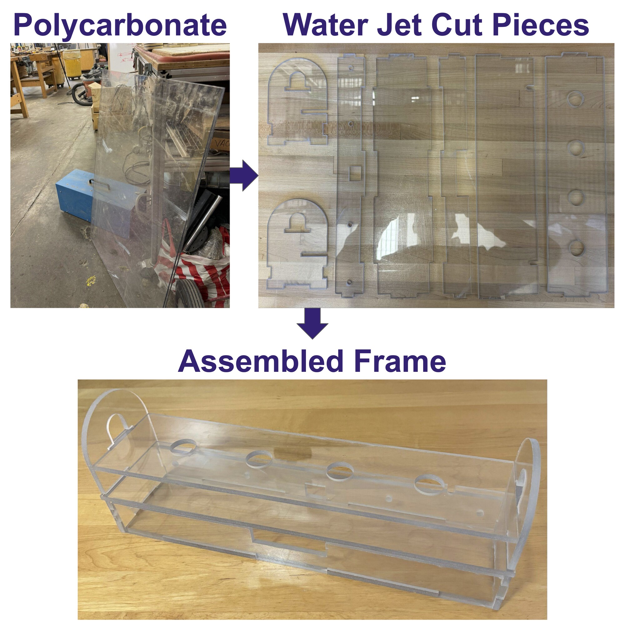
Fig. 2B. Assembling the frame.
The assembly of the frame was straightforward and the removable middle panel was extremely useful in the assembly process.
3. The Fat
Making the mold involved Computer-Aided Design, 3D Printing, and Molding and Casting skills. Looking at the datasheets for the components I wanted to use, I noted the dimensions to create a dimensioned mold (Fig. 3A). This turned out to be an extremely tedious process, as not every dimension was listed in the datasheet and I had to ensure everything was dimensioned properly so my components would fit in the mold. I ended up having to use a ruler to estimate some of the dimensions so that I could create a CAD diagram with all dimensions constrained.
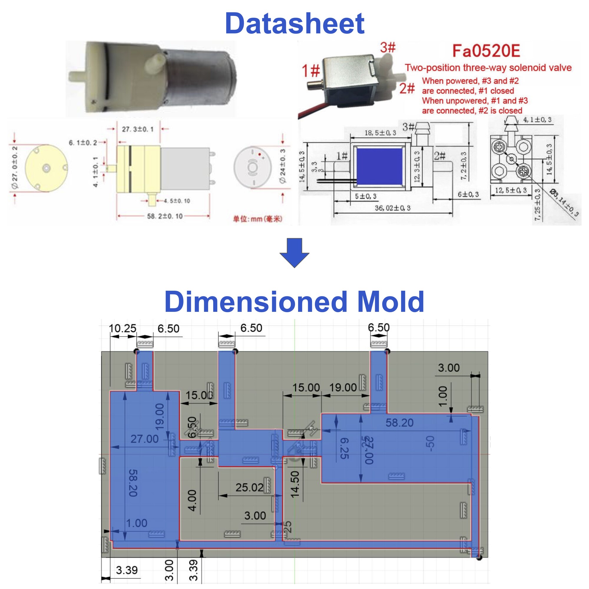
Fig. 3A. Creating a dimensioned mold.
Having the outline dimensioned, I had to ensure the mold was tall enough for the components to fit, which also turned out to be more difficult to do than expected, as I had to also include slots for the wires to insert into. Once I was confident with the design, I 3D printed the template and a removable holder (Fig. 3B). I attempted to use the Lulzbot 3D printer at my dorm, which was able to print one of the parts, but kept failing when trying to print the others. I resorted to switching printers and used the Sindoh FDM printers in the Architecture Shop, which worked well.
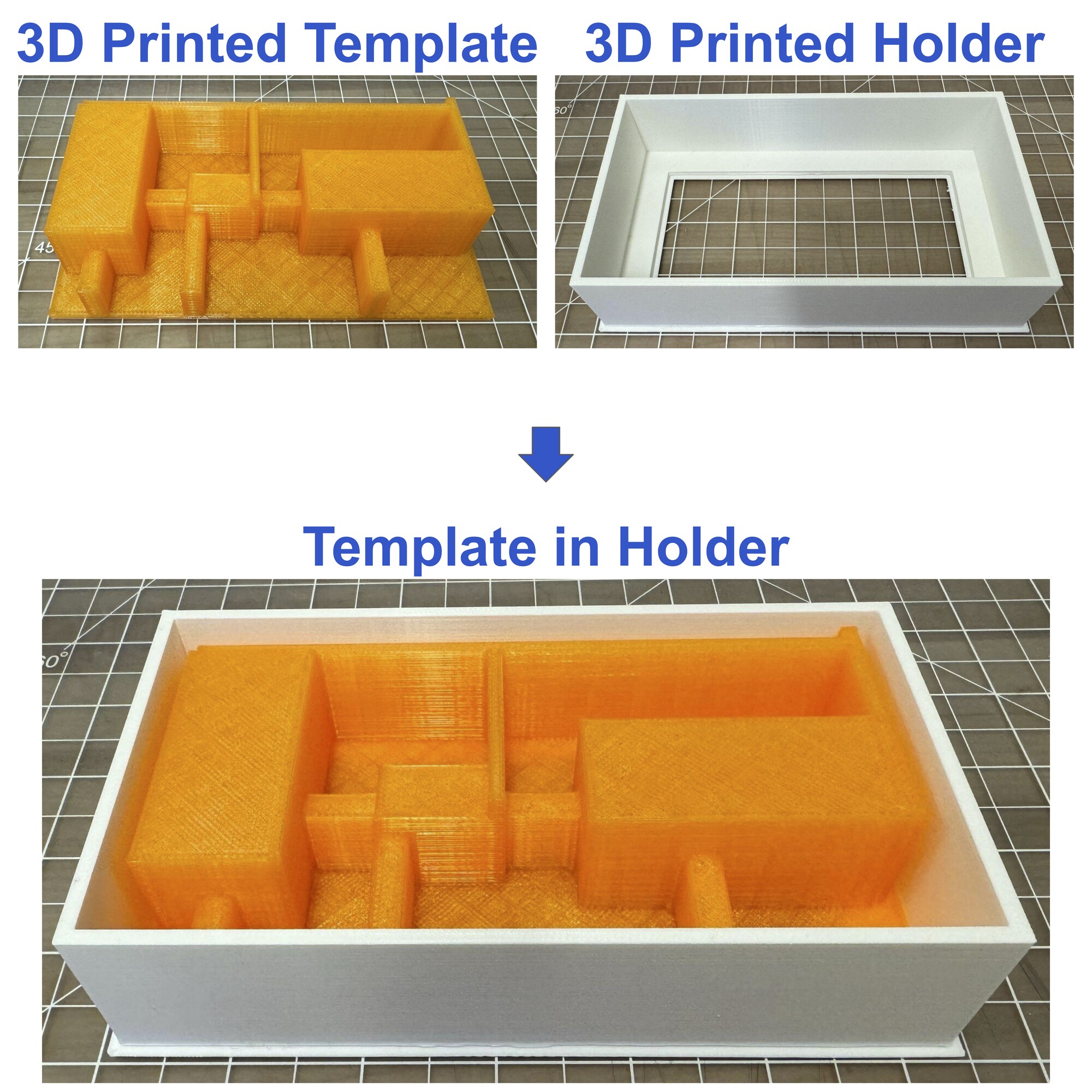
Fig. 3B. 3D printing a template and holder.
The molding here was quite easy, as I had large areas to pour into, and after curing there seemed to be no issues (Fig. 3C). A difficult part of this process was the demolding. Separating the mold from the holder took nearly 30 minutes, and it would have been impossible had I just made a joint template and holder peice. Being able to separate the template from the holder was key. I also had to be very careful in the last step, removing the mold from the template, as I did not want to tear the mold and have to repeat the demolding process again. When I finished the process, I did repeat it, but for the mold on the other side. The .stl files for the mold parts can be downloaded here, here, and here. The last note is that I did have to use a large quanitity of the silicone mold (1 full box of OOMOO 25), which turned out to be the most expensive component of the entire gut machine.
Fig. 3C. Making a mold.
After trimming the edges of the molds to clean them up and fitting them into the frame, I inserted other components, including the motors, valves, tubes, and connectors (Fig. 3D). All of these components fit as expected.
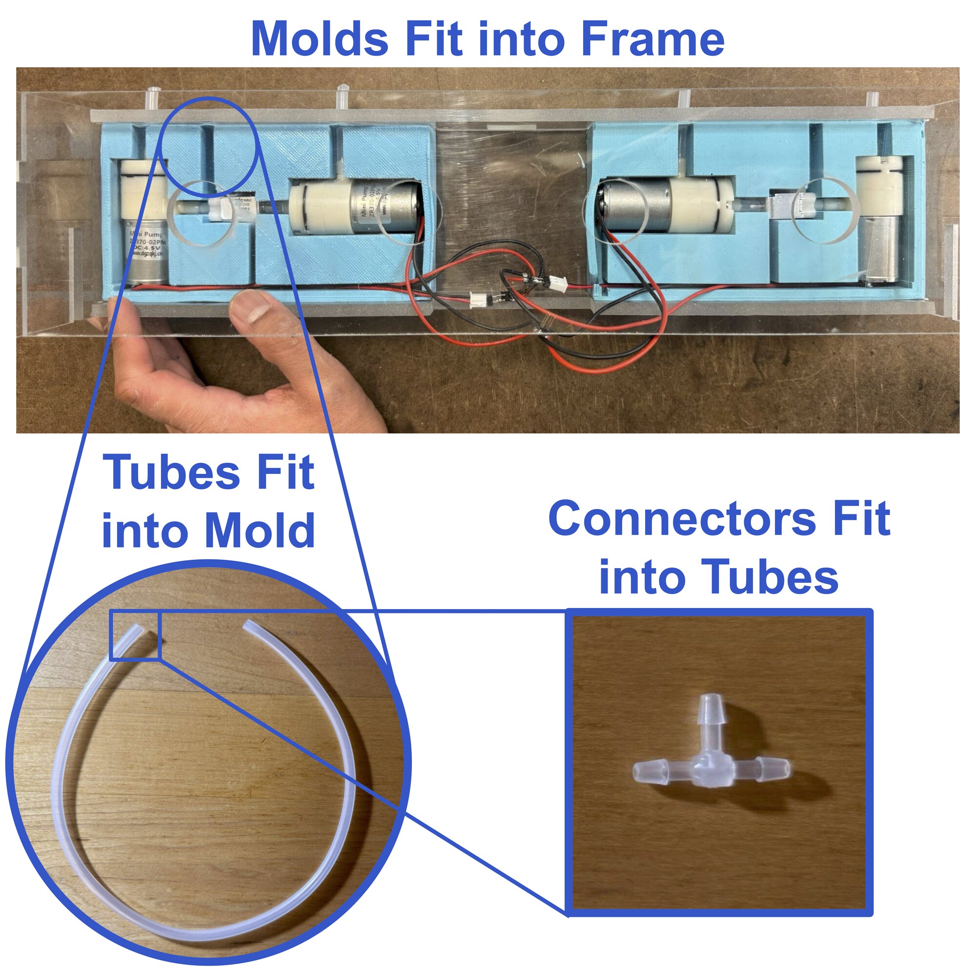
Fig. 3D. Fitting components together.
The connectors were ultimately attached to inflatable cuffs, that are actually disposable blood pressure cuffs used for neonates in the hospital (Fig. 3E). I tested the inflation and deflation of these cuffs with a syringe, and they worked well for my purpose.
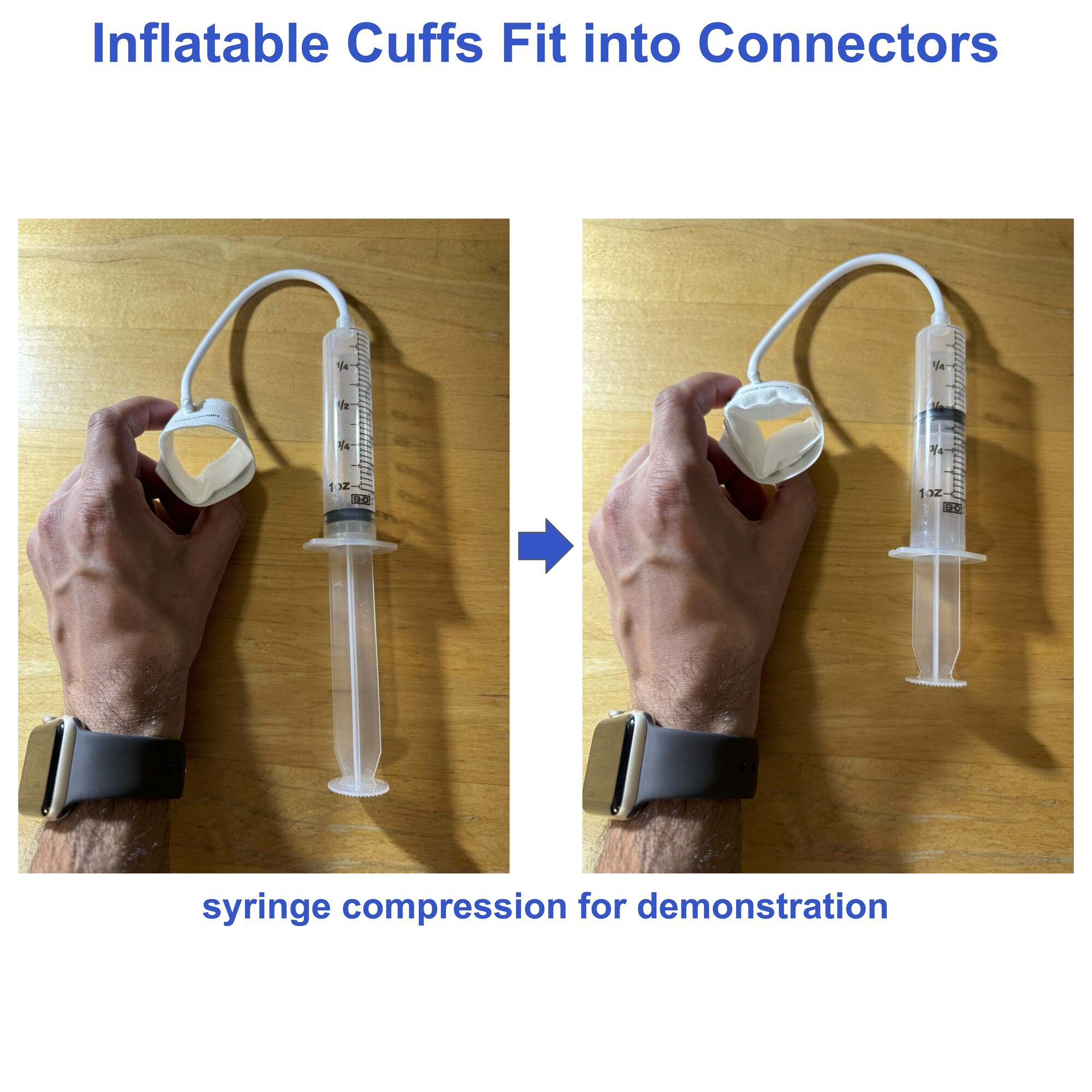
Fig. 3E. Principle of inflation.
I have never seen inflatable cuffs used for a research purpose like this, so I am excited about this innovative idea.
4. The Guts
Making the electronics involved Electronics Design, Electronics Production, Input Devices, and Output Devices skills. Electronics was the most time-consuming step by far. I went through several iterations of this circuit in previous weeks, documenting some of my failures throughout the site. Ultimatley, I created the circuit diagram that luckily had the exact number of pins on a XIAO RP2040 as I needed for all of my components (Fig. 4A). The .png files for the PCB can be downloaded here (copper) and here (profile).
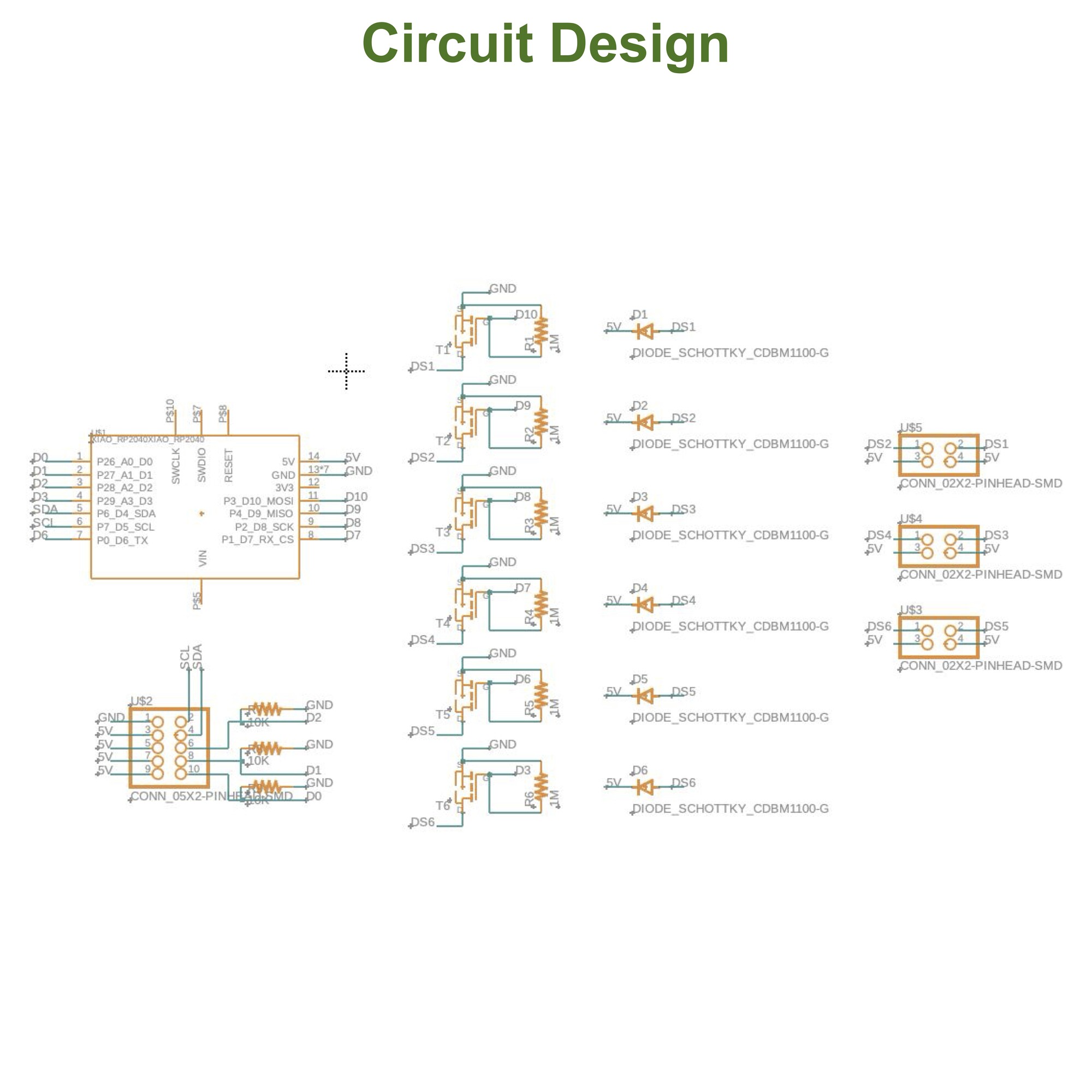
Fig. 4A. Circuit diagram.
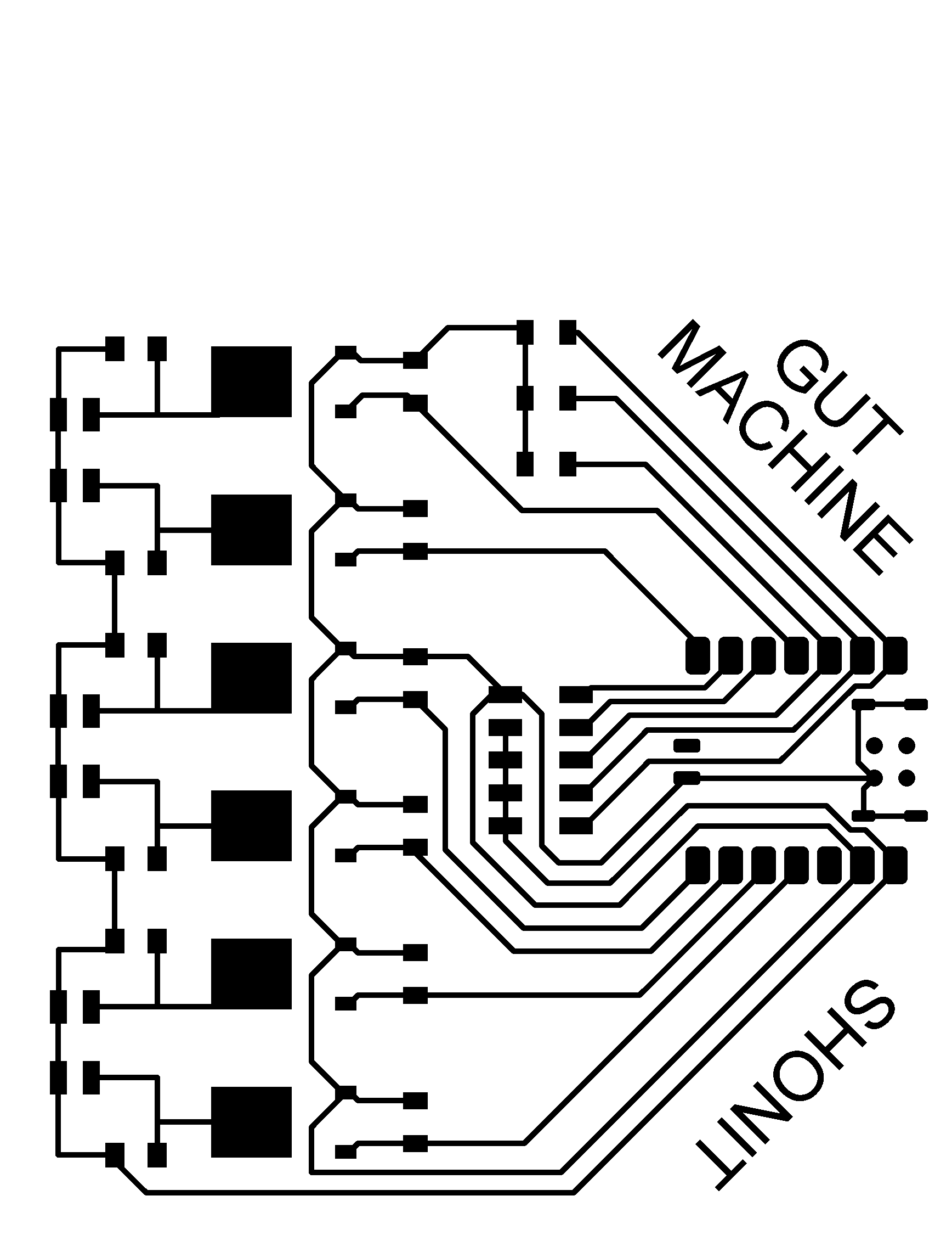
The PCB making process has grown on me a lot throughout the semester. Making the PCB layout is fun, as it is like a puzzle. I have come to appreciate the soldering process, too. Overall, I enjoyed making this final PCB, while also hoping it was the last one I would have to make for this project (Fig. 4B).
Fig. 4B. Making the PCB.
In order to connect my components to the PCB, I soldered together the wires of components to headers, creating custom headers that I could directly plug into the PCB (Fig. 4C).
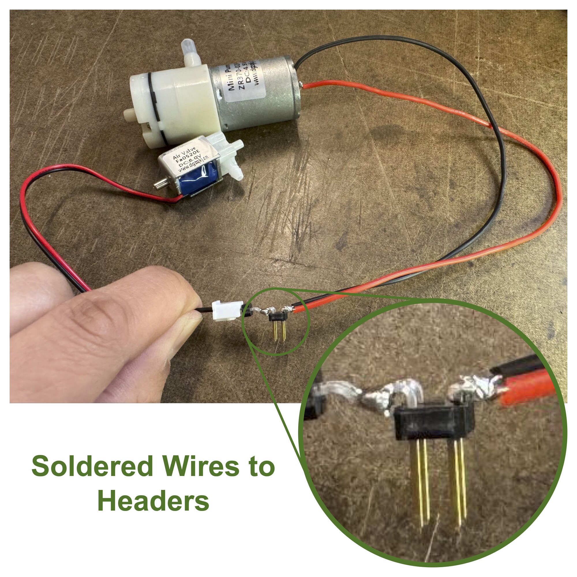
Fig. 4C. Creating custom headers.
I also modified the wires on some components to make them easier to deal with (Fig. 4D).
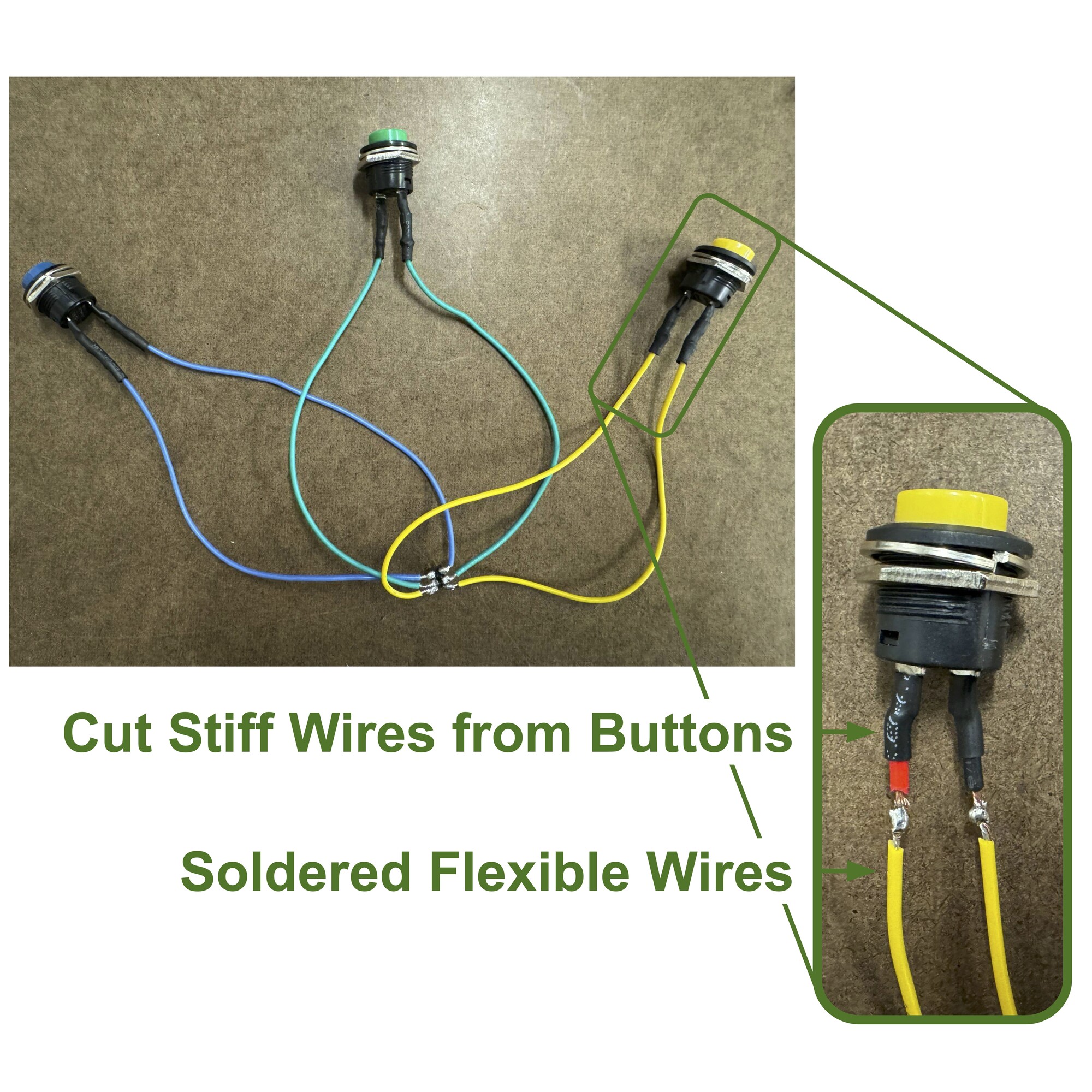
Fig. 4D. Modifying push button switches.
When ready to assemble, I connected my headers as expected, but was shocked at the mess of cables that lay before me (Fig. 4E).
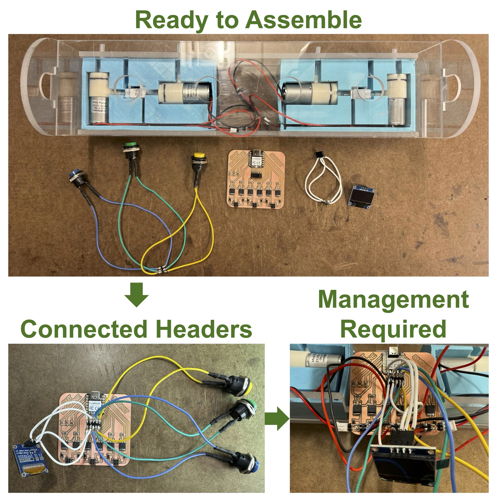
Fig. 4E. Assembling.
I was excited to devise a way to manage the cables, and once again, turned to the ease and utility of 3D printing.
5. The Abs
Making the case involved Computer-Aided Design, 3D Printing, and Mechanical and Machine Design. Starting from a sketch, I came up with a three part design and rendered it in CAD (Fig. 5A). The .stl files for the case can be downloaded here, here, and here. The idea is that all three parts would join together to form one single unit, in doing so enclosing all of the buttons and the OLED display. I took dimensions of these components with a ruler and made estimations in the CAD design, so I hoped it would print correctly.
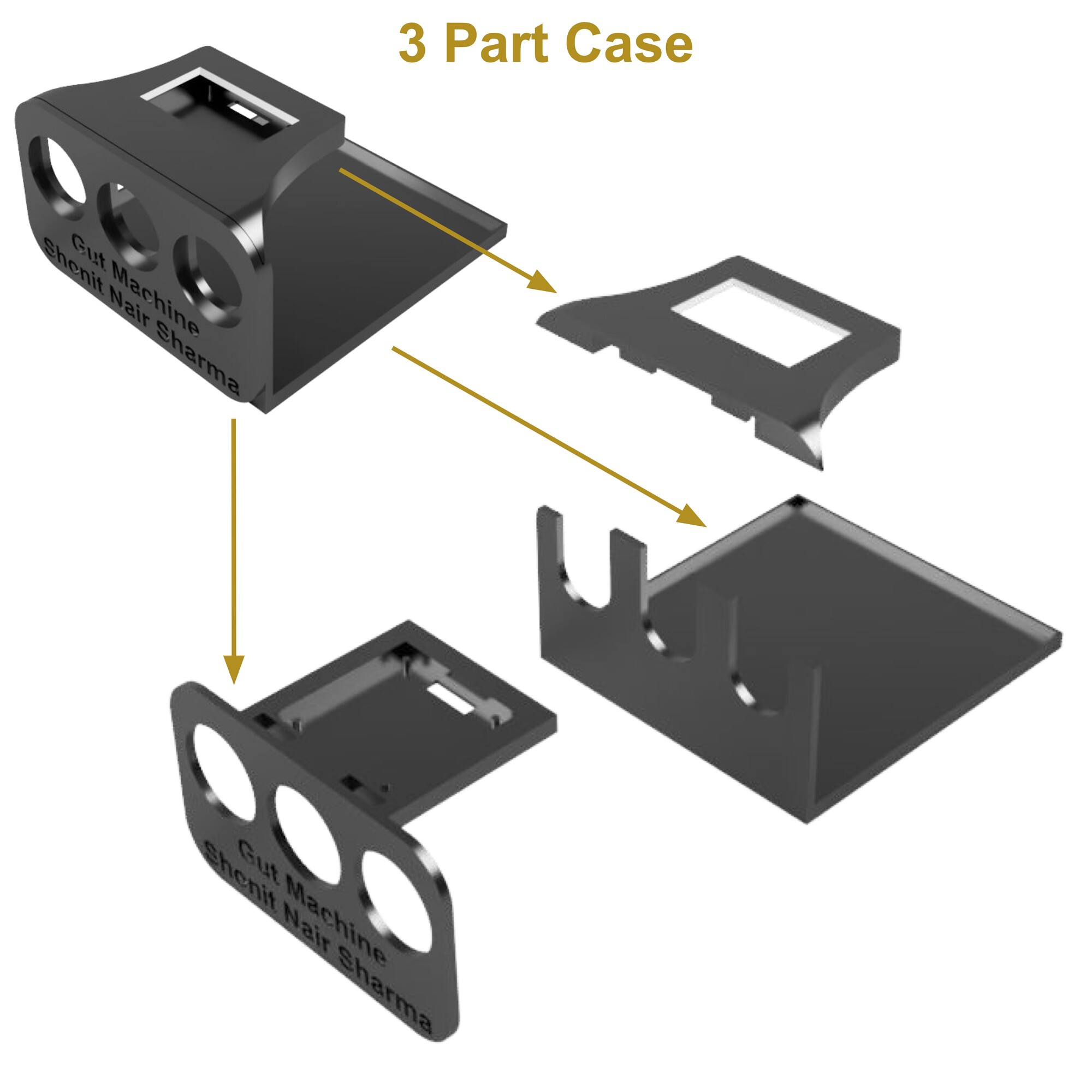
Fig. 5A. Render of the case.
I printed the parts at the Architecture Shop using the Sindoh FDM printers. To my surprise, the dimensions turned out to be perfect for the components and everything fit together as expected. The buttons and PCB slotted in very nicely (Fig. 5B).
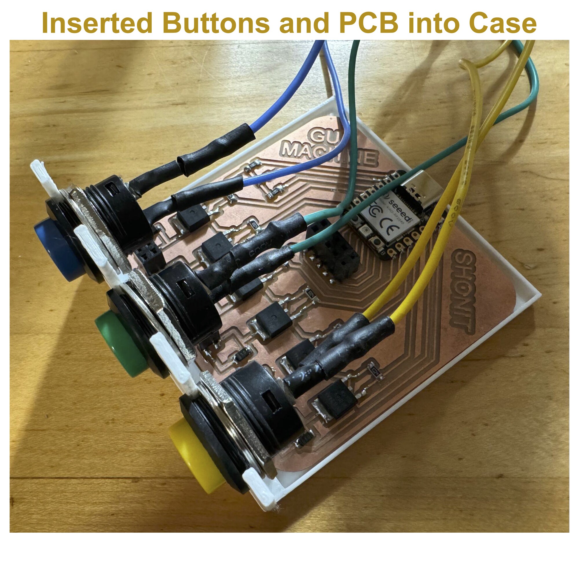
Fig. 5B. Incorporating components into the case.
I next inserted the OLED display into the slot I created for it and enclosed it with the final piece therefore completing the case, and placed it in the frame (Fig. 5C). While the 3D print quality could have been better, I was pleased with the result.
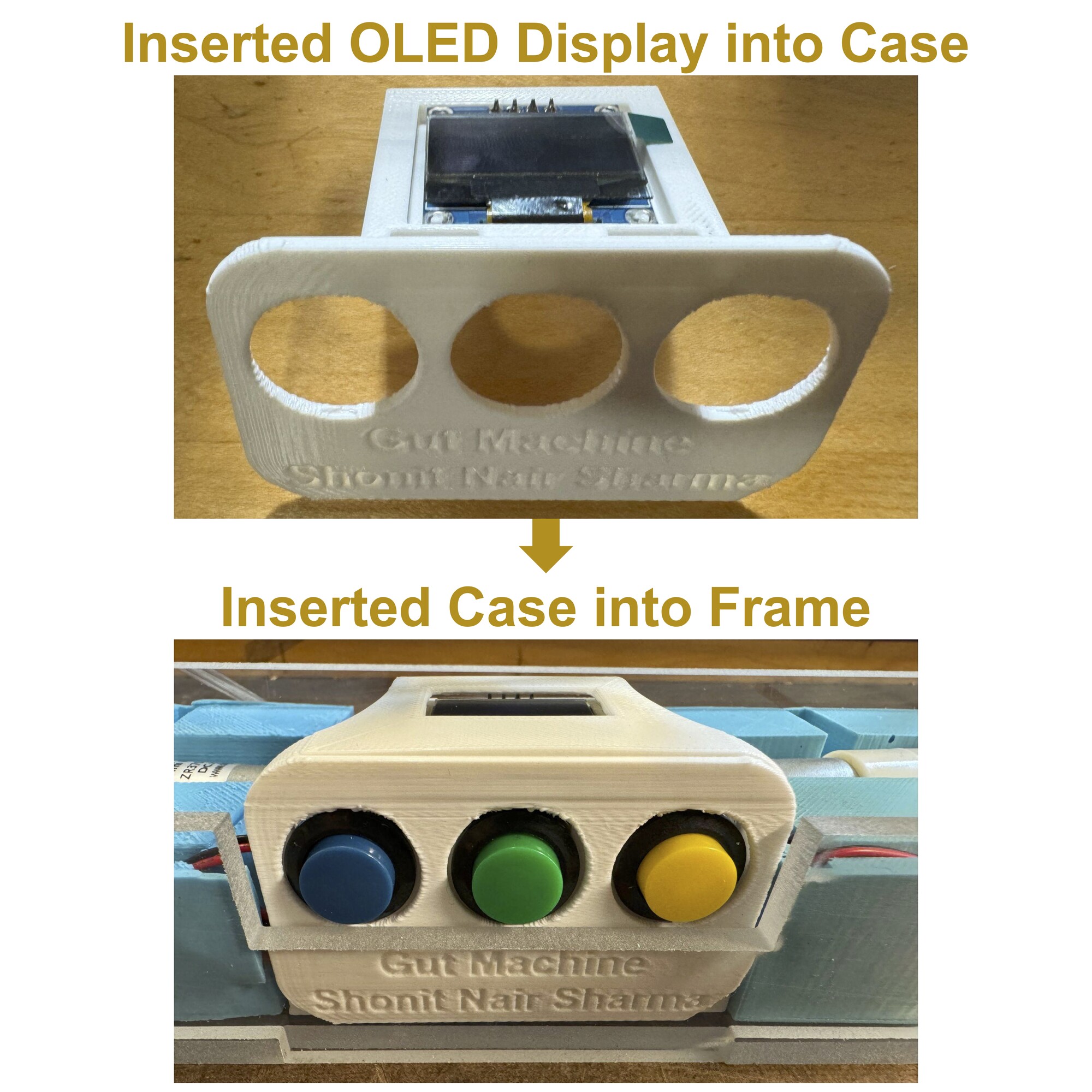
Fig. 5C. Installation of the case.
While the case contains some of the wires, I employed heat shrink tubing to manage the rest (Fig. 5D). This worked wonders, and the mess of cables was sufficiently tucked away.
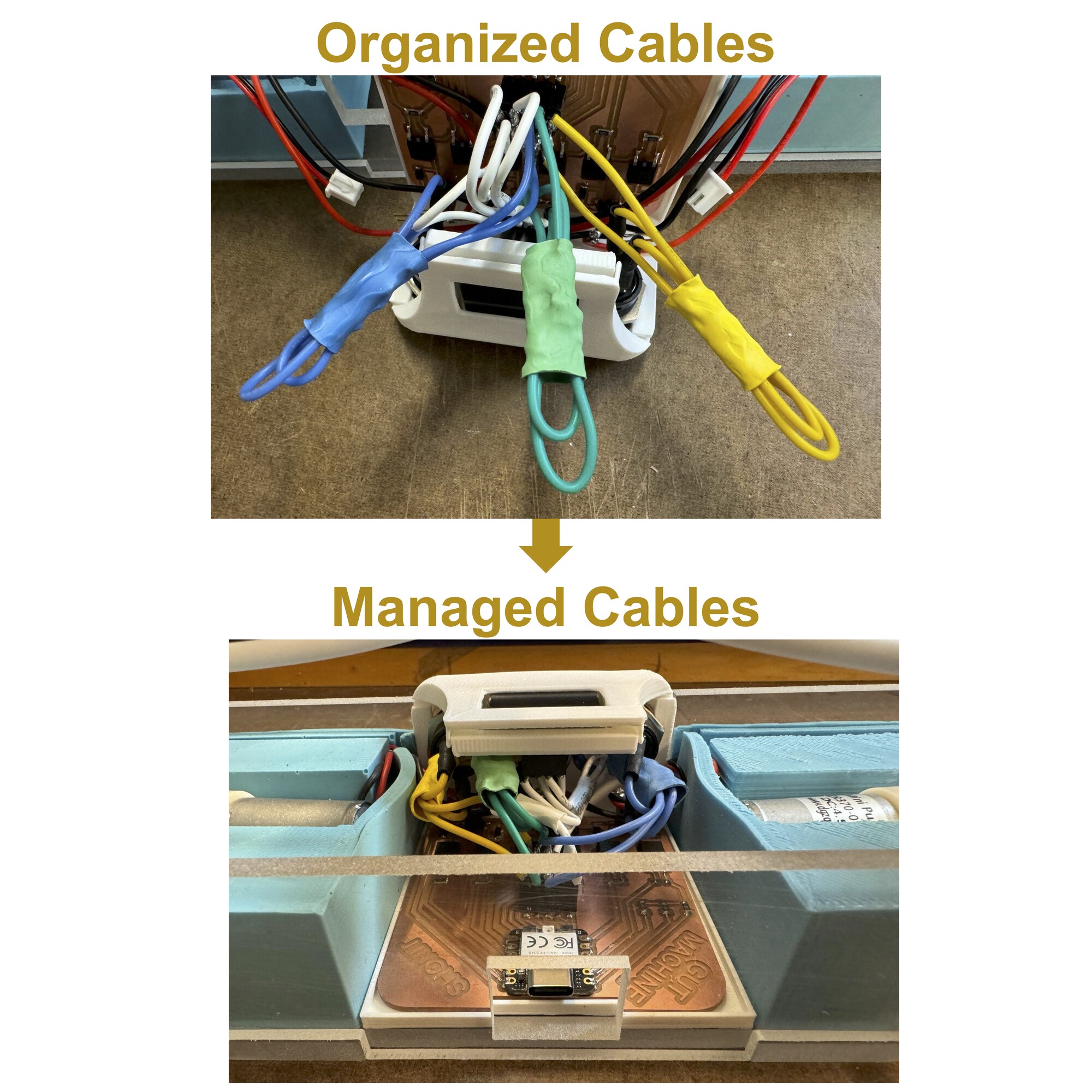
Fig. 5D. Managing cables.
Having added the case, I admired the gut machine that sat on my desk (Fig. 5E).
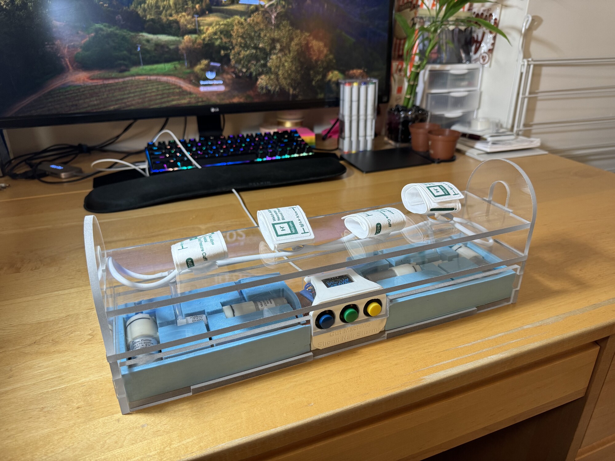
Fig. 5E. Assembled gut machine.
I was ready to upload the code and test the gut machine. The .ino code I modified from previous weeks can be downloaded here. Pressing the buttons on the gut machine, I was extremely happy to see that it worked (Fig. 5F)!
Fig. 5F. Operation of gut machine.
With the gut machine operating as intended, I planned to take it to my lab and test it with a mock intestine.
6. Discussion
A few side notes before I get to final operation of the gut machine. I came up with the idea of the gut machine before even applying for "How to Make (almost) Anything," and saw the opportunity to learn the skills necessary to execute a project like this. When I decided to apply, I was motivated to achieve my vision for the project. At the beginning of the semester, while researching how I create the compression necesssary for the gut contractions, I explored the possibilities of mechanical, pneumatic, and even textile systems. I ruled out mechanical contraction, as I wanted something more fluid, and while a structure such as a mechanical iris can close radially, I would need many of them to have them span the length of the intestine. While a textile-based system, such as artificial muscles, would surely be interesting, they posed a problem in that I would likely not be able to create the different types of contractions I hoped for. Settling on a pneumatic system, I explored how I could manipulate air to serve as a pump and vacuum. I learned about the FlowIO system, and applied through the website to acquire a device. I managed to get approved for the device by creator Ali Shtarbanov and eventually ended up borrowing a device from Ozgun Kilic Afsar. Taking apart the FlowIO device to see what it was comprised of, I realized I did not want to rely on a device for this project that I could not troubleshoot swiftly, and furthermore decided that making my own pneumatic regulation system would be much more satisfying (Fig. 6A).
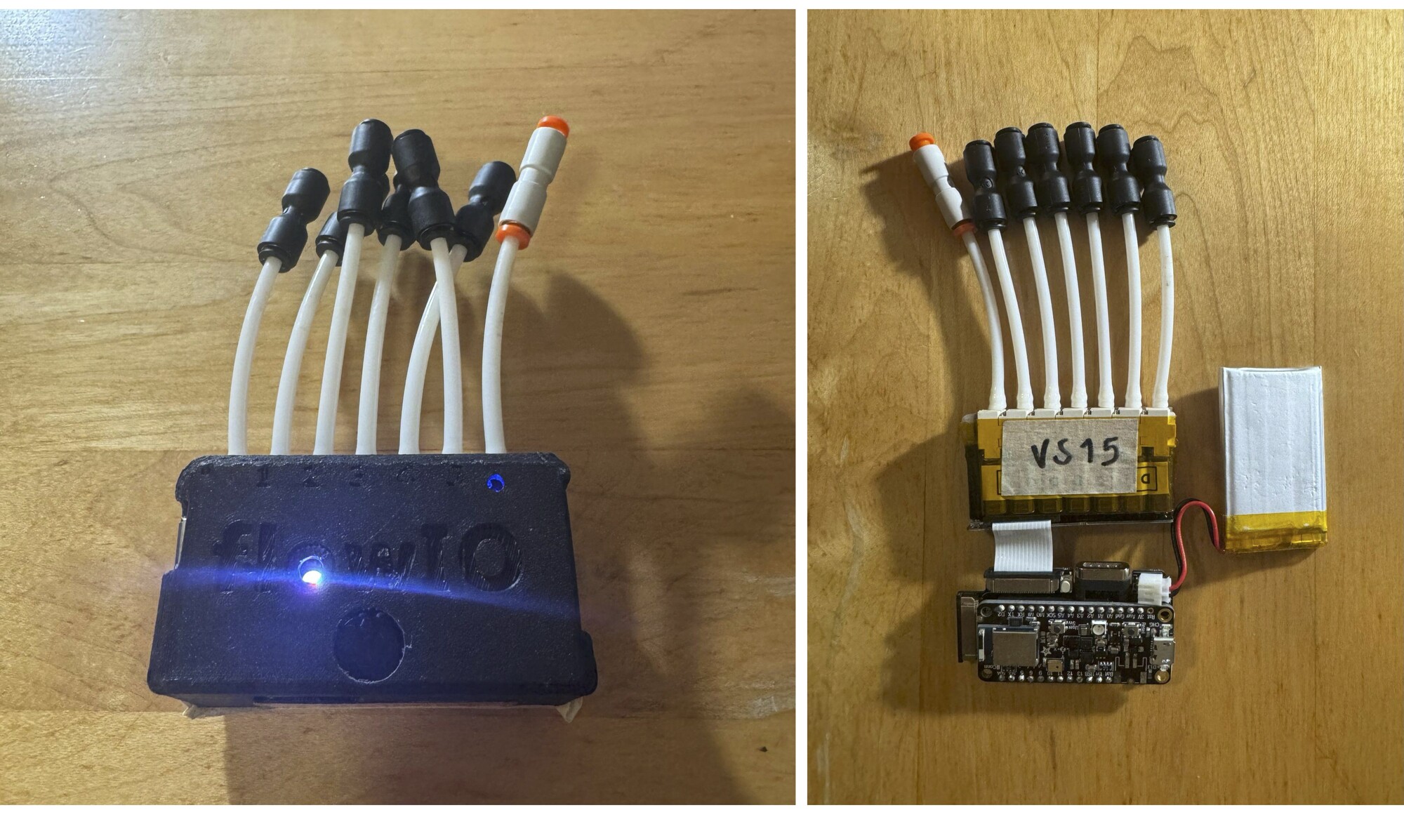
Fig. 6A. FlowIO device.
Researching what components I needed to make my own system, I bought parts from various online vendors, and borrowed others from various labs at MIT. I estimated the total cost of the gut machine based on all the parts used, which turns out to be just below $150 (Fig. 6B).
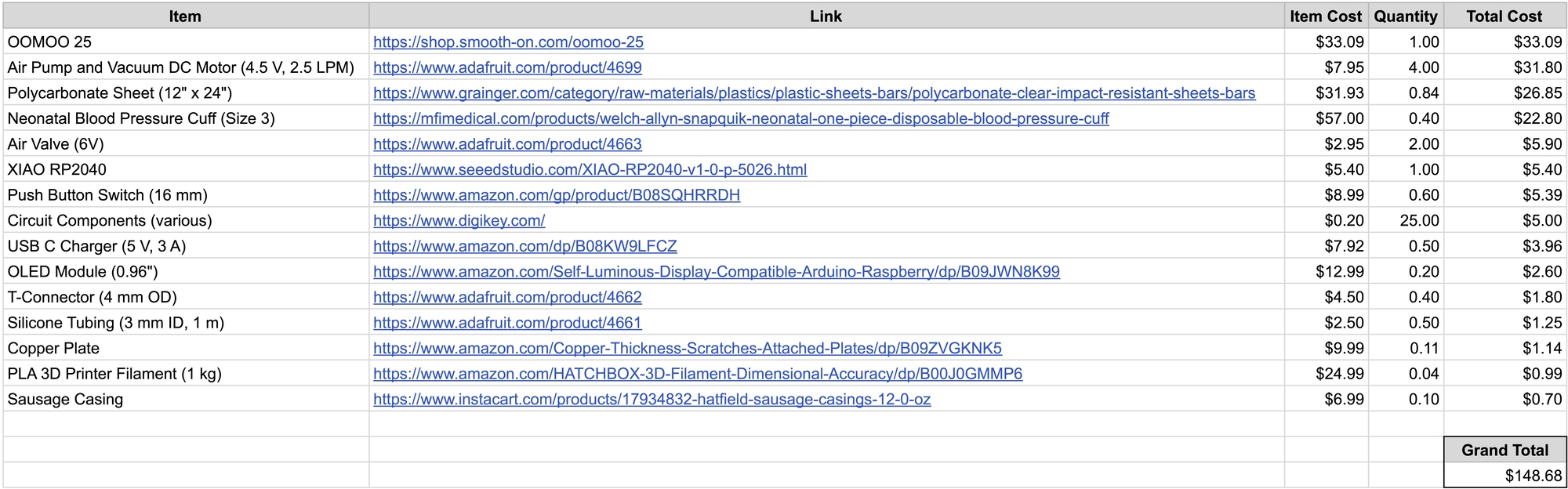
Fig. 6B. Cost of gut machine.
While the gut machine turned out to be more expensive that I thought it would be, its proposed utility far outweighs its financial cost.
7. Conclusion
Taking the gut machine to my lab, I set it up with a 12" long glycerin-filled sausage casing, a true-to-size replica of a human small intestine (Fig. 7A). Additionally, I clamped the ends of the sausage casing with hemostats, to prevent leaking.
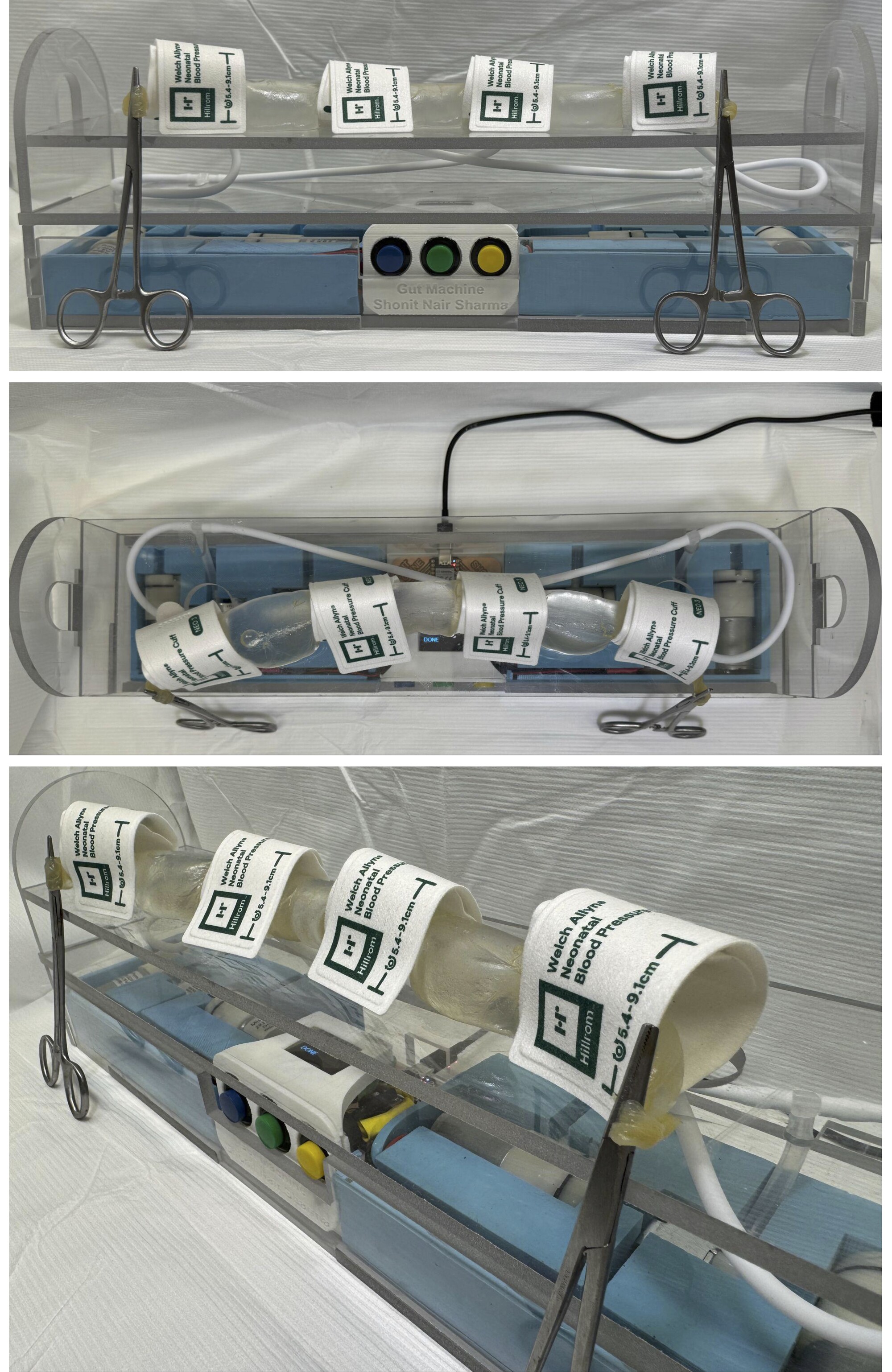
Fig. 7A. Full setup with the gut machine.
I placed a vitamin capsule (filled with colored water beads for visualization) in the sausage casing, and started the gut machine. I was able to see the contraction-induced movement of the pill down the length of the gut (Fig. 7B)! I did notice that the movement would slow or stop at the regions between cuffs, necessitating additional cuffs to be added in the future. This would be quite easy as I can just use tube connectors to add additional cuffs.
Fig. 7B. Tracking pill movement with the gut machine.
The ideation, design, and creation of the gut machine was a very rewarding process. Not only did I learn a lot about making, but I also ended up with a device that will help advance my research to design robotic pills to improve drug delivery. The gut machine is programmed to squeeze with different modes of contraction (e.g. segmentation, peristalsis, both) and can be tuned to achieve physiologic metrics (e.g. amplitude, frequency), which is key for testing robotic pills. Lastly, with validation, the gut machine can be an alternative to an in vivo model of gut contractions, which is an expensive and lengthy surgical experiment that often necessitates sacrificing the animal. Therefore, with the creation of the gut machine and its use to further the field of drug delivery, I hope to save more that just one life.