Week 9: Output Devices
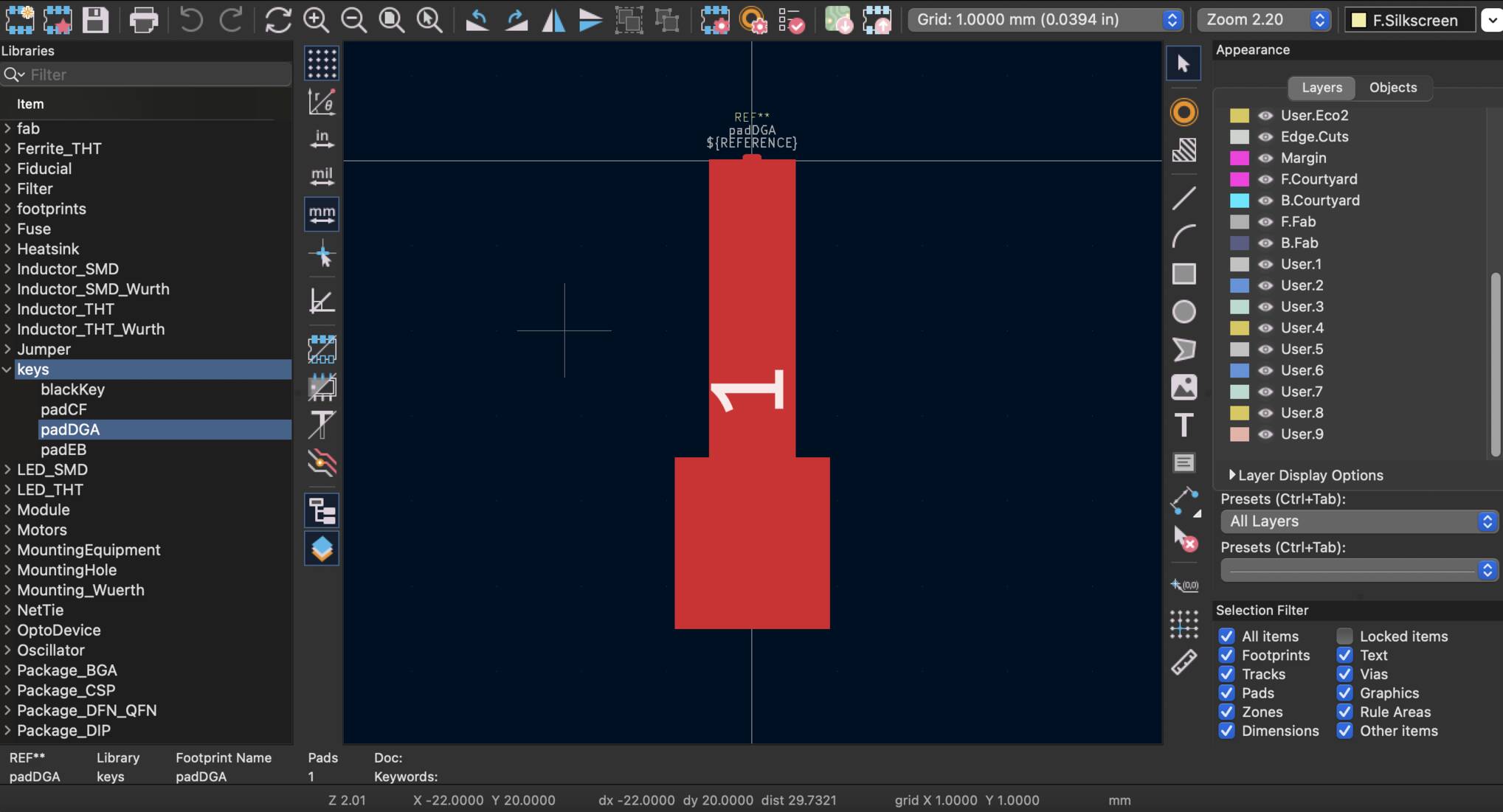
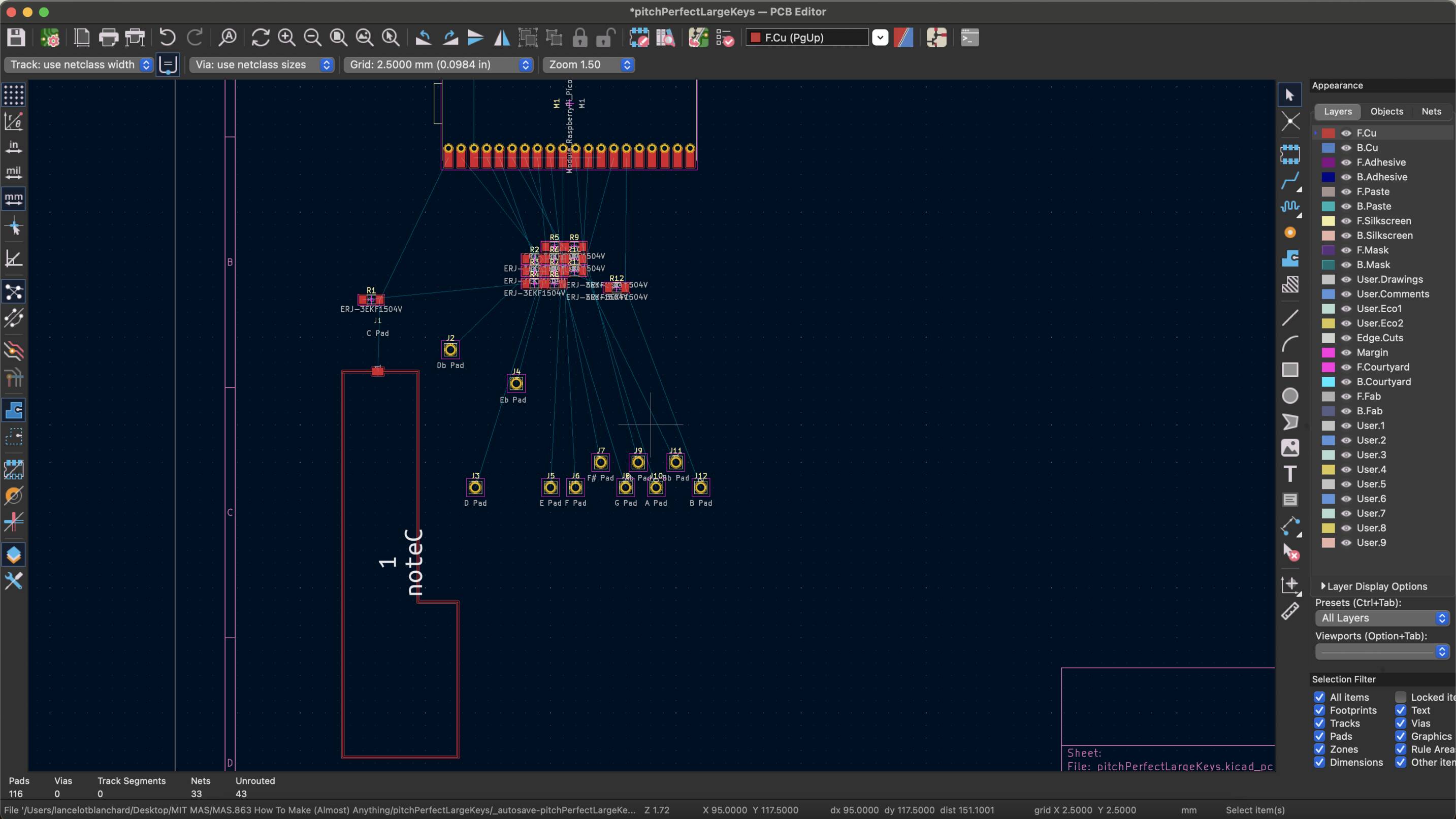
This week, I knew from the start that I wanted to expand my project from last week by adding a speaker to my keyboard. I started by prototyping directly on my 7-pad keyboard, and I obtained some interesting results, but the small size of my keyboard annoyed me and I wanted to move to a bigger, full-sized keyboard. For this one, because it involved 12 keys, I needed to use the Pico and take advantage of the many digital pins of the RP2040 chip. I settled for the Pico W because I could not find any standard Pico, even though I am not using the wifi capabilities of the controller. I started by designing a new version of my keyboard on Kicad. To do so, I had to manually design the footprints for my pads in order to make them look like keys that could actually be played, akin to my design from Week 5. For my 1 MOhm resistors, I opted for the SMD resistors from the inventory instead of the through-hole resistors from my previous prototypes, which were not the most aesthetically pleasing.

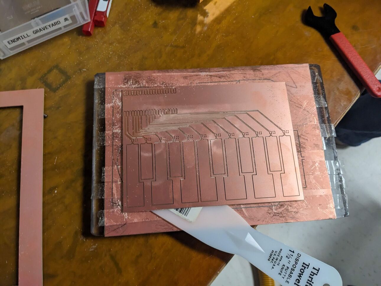
When starting my milling process, I encountered a few problems including one that is starting to become more and more familiar throughout my HTMAA adventure: my design was too big. I therefore had to resize my keys and board and managed to make it fit on the 160mm x 120mm boards that were given to us. I started the milling process, waited for 2 full hours and finally obtained a very satisfying result.
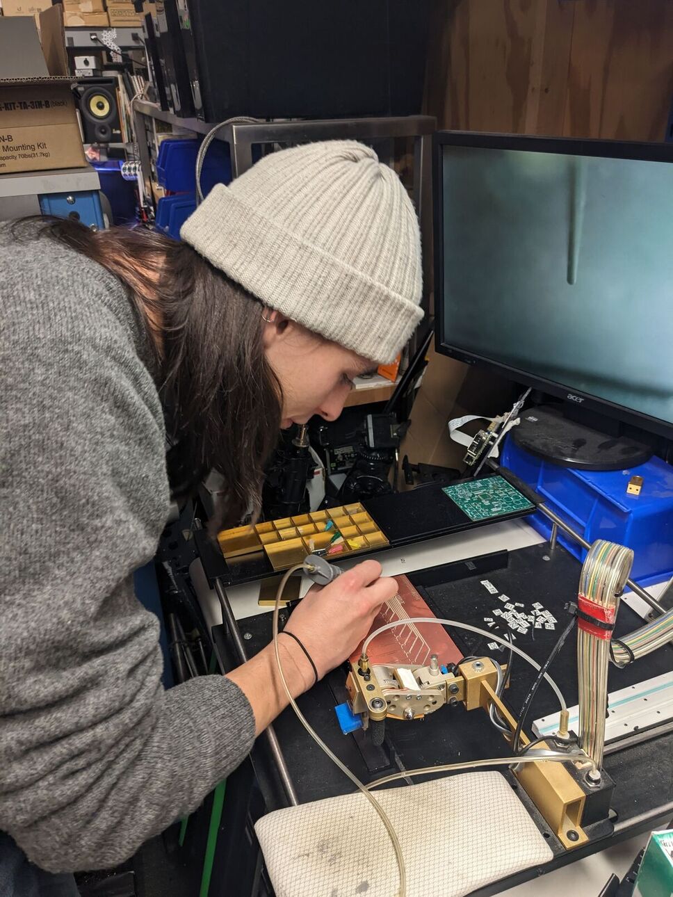
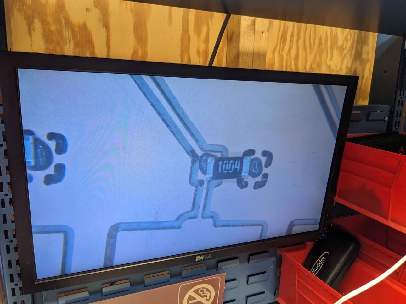
It was then time to start the soldering process. I was very intimidated by the SMD resistors and my labmate Perry kindly taught me how to perform reflow soldering using our lab's equipment. I found the process to be very fun and I successfully managed to solder all resistors.

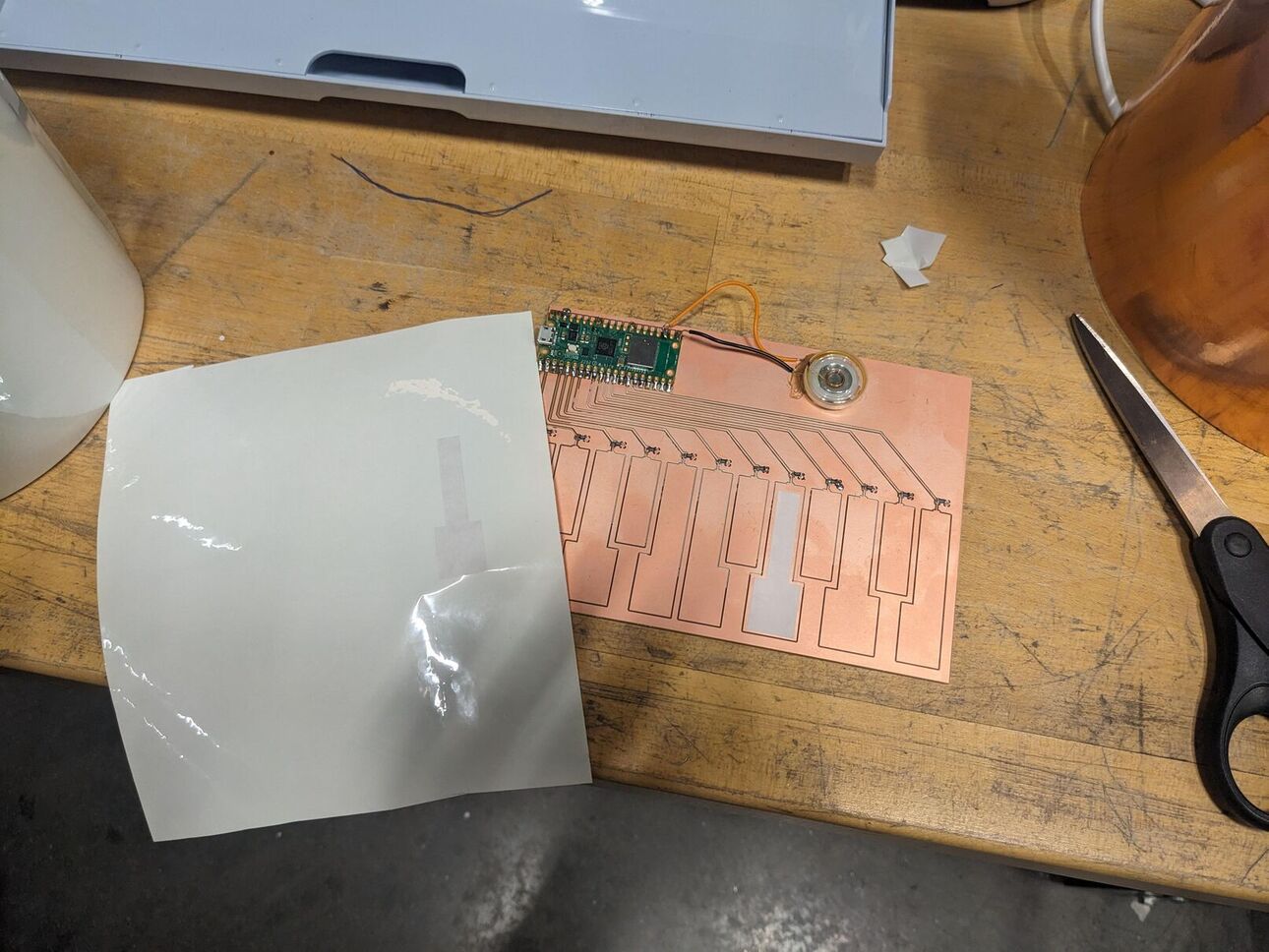
Then, it was time to actually add the output speaker. I found some speaker and I wired it manually onto my board. I should have probably included some traces in my initial design but hey, at least my board looks more edgy now. In order to fix the speaker, I used hot glue to glue it onto the board, and soldered the wires directly to the Pico. Then, I wanted to make the keyboard more aesthetic, and I decided to re-use my design for the footprints and use the vinyl cutter to cut some keys to put on top of the plate.

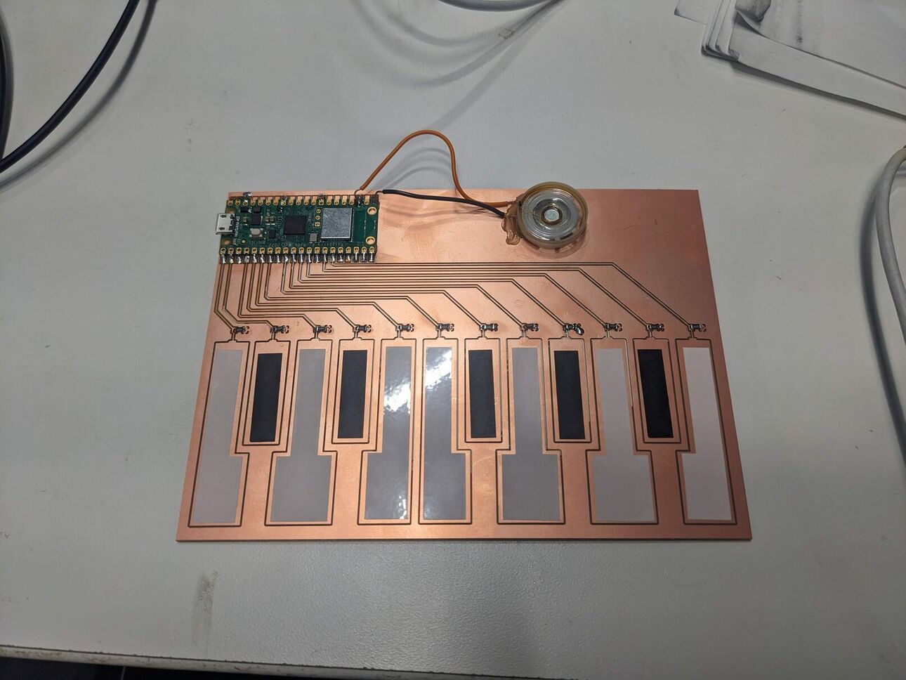
Finally, it was time to program my board. I used CircuitPython once again, with the same input libraries than last week. For the audio out, I used the pwmio library to generate some square waves at a given frequency to be played by the speaker. I associated every note to its frequency and it worked like a charm! The code is available here. Finally, I obtained this keyboard, which, for one of the rare times in my HTMAA adventure, is actually fully playable. One issue: the volume is pretty low, and I imagine that this is due to the output being at 3.3V. In the future, I'd love to add a signal amplifier!
Notes to a future me (learning outcomes):
- CircuitPython (or MicroPython) makes prototyping very easy.
- Reflow soldering with SMDs makes you feel like you're a real scientist.
- Once again: Size matters, design accordingly.