
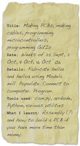


Here’s what happened ...
In week 3 I successfully created my first ever PCB using the Modela mill. I’m more used to sending Gerbers to a fabrication plant for factory manufacturing, so the “local fabrication” option was definitely a new experience for me. In week 4 I built two cables (serial, parallel) to interface between Linux and the PCB. I’m sure there must be a better alternative to that programming clip ... further thought required. I successfully programmed the first hello world board with the prewritten hello1 code. This program simply displayed the output “hello world” multiple times on the screen of the PC.
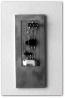
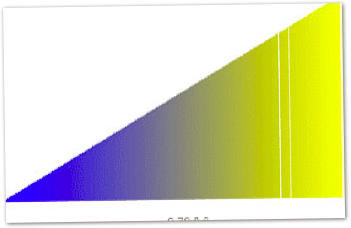
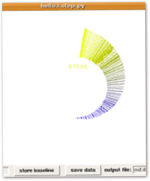
For week 5 I built and populated the How to Test Anything (“hello3”) PCB. This was another simple board (see above) with only a few components. I delved into assembly for the ATTiny processor, focusing in particular on the ADC functionality. I wrote Python GUI code to create a visually interesting representation of a voltmeter test output (see above, barcode-style output and spiral shell-style output). The barcode output featured text which change size and position in accordance with the magnitude of the measured voltage. The text label on the spiral remained the same size for clarity but followed the location of the extension bars as appropriate. I took advantage of the Python math library to achieve this effect (simple Cartesian-Polar transformations, a limited amount of trigonometry).
In the process, I collaborated with Stephanie to comment Python code and I collaborated with Neri on the various GUI representations.