


Here’s what happened ...
(I worked with Matt Trimble this week)
Step 1: Learn about the problems from last week
Last week’s keypad didn’t not work, but it didn’t work flawlessly either. Individual keys were operable, but the entire keypad as a unit didn’t give the results we wanted. An hour with an oscilloscope taught me why: signals on adjacent traces would interfere with one another, causing serious signal attenuation and degradation of information by the time it reached the microcontroller. It wasn’t possible for the microcontroller to figure out which button had been pressed because the information it needed simply wasn’t there. Lack of a ground plane and no signal conditioning didn’t help either.
Step 2: Understand the problem space better
Last week we just guessed at an acceptable pad sizing, but we had no idea if it would really work. So this time round we decided to take a more rigourous approach: try out a selection of different pad geometries and find out what the impact was on the signal quality. We built several different pads and attached them to a hello3 board. The results: geometry doesn’t matter, but **proportions** do. Scaling up all dimensions while keeping the same proportions seems to make for signals which are of approximately the same quality.
Step 3: System architecture & design for test
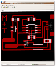
We wanted to maximise the chance of the system working. That required a modular board and software design with good testability:
ON INPUT BOARD:
a) Three hello3 circuits, each of which can be individually tested and has its own serial port. Each can be used either with built-in pads or with external pads (this design decision was intended to mitigate future potential interference problems if necessary).
b) A gateway micrcontroller which would monitor each hello3 and determine if a key had been pressed.
c) A Molex4 connector which links the gateway to the output board. The arbitrator sends a byte to the output board according to which key has been activated
ON OUTPUT BOARD:
a) Speaker and microcontroller
a) Speaker and microcontroller
b) Molex4 connector which links to the input board
c) Software to interpret the byte sent by the gateway processor and cause one of three tunes to be played as a consequence
Step 4: Build and test
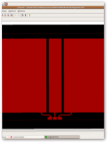
Fabrication of the output board was trouble-free. Test showed that it functioned as intended. We programmed different tunes. We didn’t fully test the serial connectivity because we didn’t have the input board ready in time.
The Model mill broke over the weekend, which meant we couldn’t fabricate the new input board when we needed to. We tried the vinyl cutter, but the traces were sufficiently complex that it was impossible to pick of the unneeded copper without causing irreparable damage. Eventually Matt managed to fix the Modela but the 2-hour time period needed to fab the output board proved a problem. In the end, we had all the components ready - boards fabricated and populated, software written, connectors ready - but we didn’t have time to integrate and perform the final test.
So close!