


Sense_files/shapeimage_5_link_0.png)


Here’s what happened ...
I worked with Matt Trimble to design and build a keypad to provide input signals for the ATTiny. We decided to use capacitance-based sensing for enhanced robustness and because of code reusability from the Hello3-step project.
Part 0: Requirements and System Architecture
The requirements listing was straightforward:
a. System must capacitively sense whether or a single button (of nine total) is instantaneously being activated by the user
b. System must use ATTiny13 microcontroller
c. System must interface with PC and display an on-screen representation of each button press event
d. System must operate with minimum lag / time delay
e. System must be usable by multiple operators
f. For ease of fabrication, all PCBs must be single-layer, using 0-ohm resistors where necessary for trace crossover
Following a short feasibility study, we decided that the system architecture needed to include the following subassemblies:
a. Nine-button keypad incorporating pads for capacitance-based sensing. The “keys” are numbered 1 through 9 in a layout matching that on a digital telephone. The keypad is made from FR4 since it is essentially a PCB of its own
b. Eight-lead cable to interface with keypad. Seven of these leads are used for signals. The cable features detachable Molex connectors at each end in order to permit future use of different boards and/or keypad designs. This promotes design flexibilty and provides an upgrade pathway
c. PCB incorporating ATTiny, appropriate routed to Molex8 for keypad and Molex4 for PC communications.
d. Microcode to pulse each of the keys in quick succession and measure response using the ADC
e. Python code to interpret the output of the ATTiny and display notification of key press accordingly
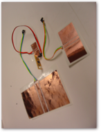
Part 1: Keypad
Each keypad button incorporated three pads: sense, step (also known as “shield”), and ground. The shield can accept a step from a digital output line, while the sense pad needs to connect to an ADC pin. The pads are sized such that a person’s finger can be easily placed across the shield. The pads are arranged to be both row- and column-addressable. Photos and schematic to come.
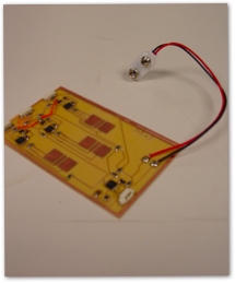
Part 2: Eight-Lead Cable
This was a simple soldering/crimping operation. One 8Molex connector on each end. Photo to come.
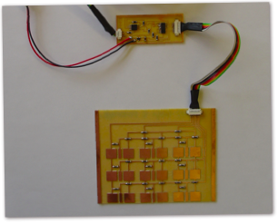
Part 3: PCB with ATTiny
This new design was completed in Eagle. It incorporated the ATTiny together with a decoder to address each row in succession. Schematic, layout and photos to be added.
Part 4: Microcode
Using Hello3-step.asm as a foundation, new code was developed to pulse each key in succession.
Part 5: Python code
The Python code not only interpreted the microcontroller’s output but also included a calibration routine to self-check the capacitance changes between a “non-depressed” button and an activated button. This makes sense because the step response is largely user-specific.
Results of Testing
The keypad didn’t not work. Oscilloscope testing clearly showed significant and measurable differences between a depressed key step response and that of a non-depressed key. These differences were picked up by the microcontroller and we had at least one key working reliably and showing output on the PC. Since the keypad and associated circuitry is essentially symmetric, one should be able to get all 9 keys operational given time and motivation.