
I felt quite fortunate that the schematic for the ISP programmer had already been given to us. My favorite part about this lesson is that I got to spend all of the time focusing on how to use the PCB miller, and the hands-on training of soldering stuff to the board. I often get sick of dealing with the iterative process of designing, fabricating, and then having to tweak the design to match the reality.
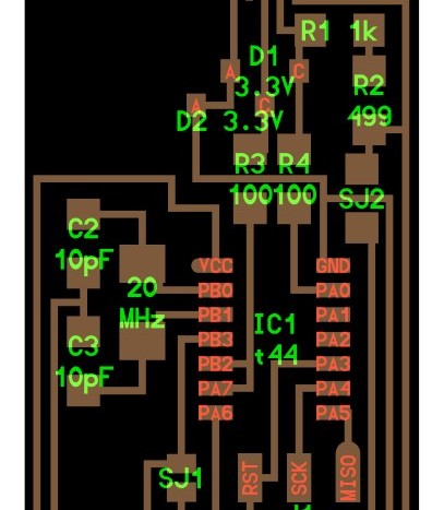
The circuit design for FabISP
For the most part, it was smooth sailing. I got held back on the first step, because I accidentally forgot to change the PNG while performing the cutout step. So, here we go, how to make your own PCB:
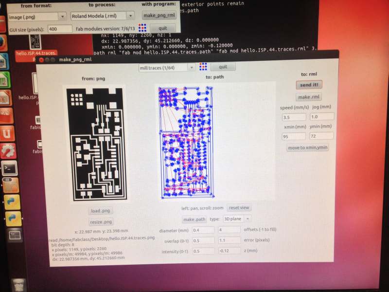
Step 1 – Make a path from the PNG
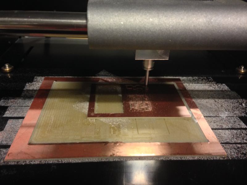
Step 2 – Make sure you’ve got the right pitch endmill, and send it to the miller
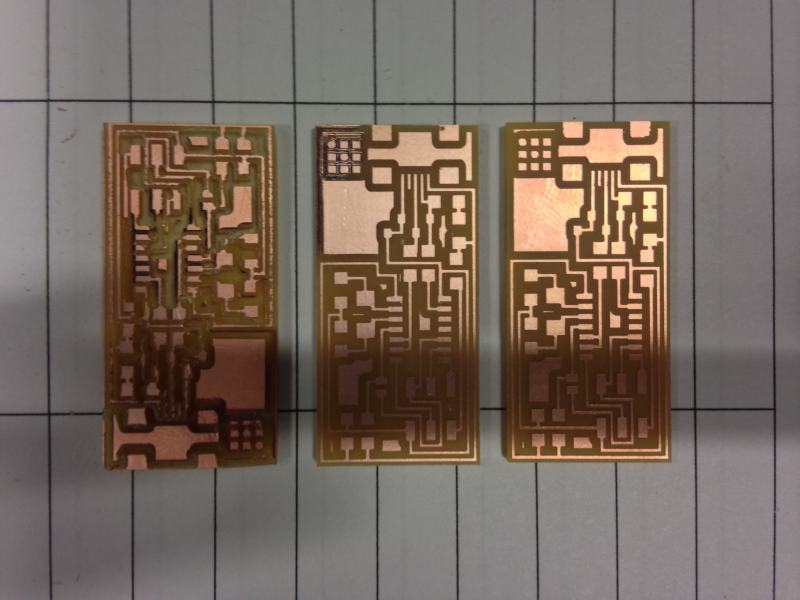
Step 3 – DON’T TRY TO CUT OUT WITH THE ACTUAL PCB DESIGN PNG OR YOU’LL GET THIS

Step 4 – Replace the endmill piece if it breaks

Step 5 – After the milling process is done, lift your board up gently and get it out of there
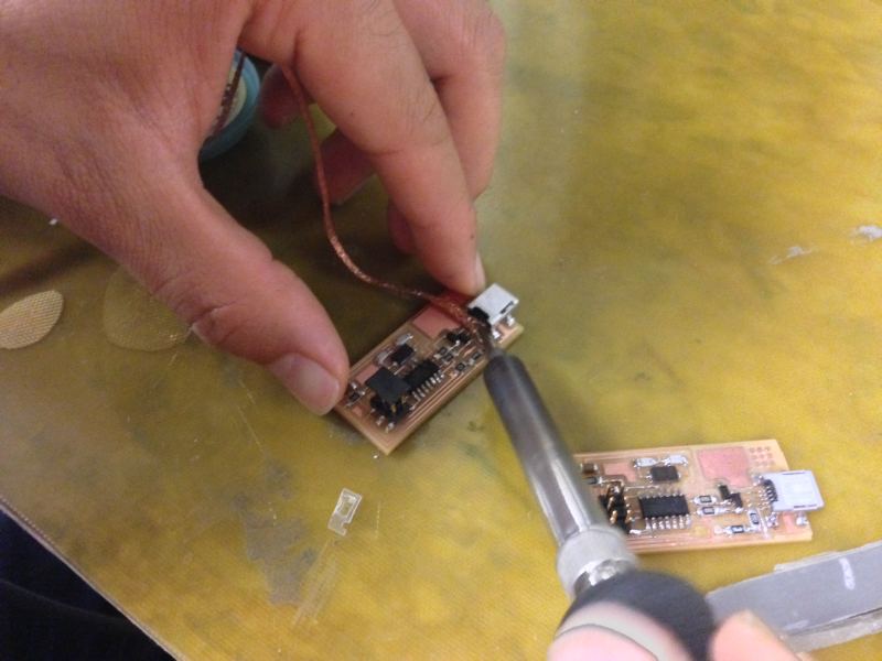
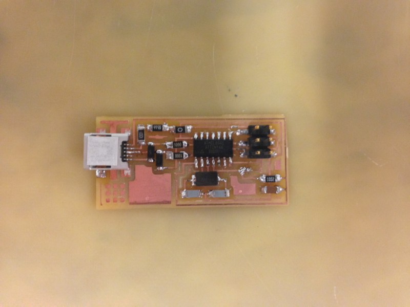
Step 6 – Solder the parts on the board, one by one
Step 7 – Respect the board
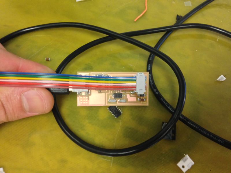
Step 8 – Make a cable with the vice grip and program your board with someone else’s board
Step 9 – Enjoy your weekend like this guy, because you’ve finished your project WAY early!
So, that’s pretty much it.
Things I learned:
- I’m better at soldering than I used to be. I was really nervous about this, because I remember it being really hard.
- CHANGE THE PNG before you do the cutout.
- Make 2 boards, keep the other for a rainy day.
- Keep an eye on the machine, because the endmill piece might break as it did for me.
Ermal
UPDATE
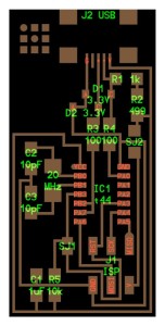
Since I had free time, I ended up making another board using Valentin Heun’s design from previous years. This design is nice for two reasons: you can program and then remove the external board to after instead of desoldering the bridges, and it plugs directly into your USB port without a cable!
This one DID have some issues, however. I was able to program it, but after it was programmed, the PC would not recognize the FabISP USB device properly. I remembered that another student had a similar problem, and the suggested correction was to check the connection to the crystal. This is because when the device is programmed, the ATTY microchip switches to using the crystal as a clock signal.

After some debugging, making sure there were no floating components, it all worked and I was able to program it successfully!