Week 11: Output Devices
This week's assignment was to "add an output device to a microcontroller board you've designed and program it to do something".
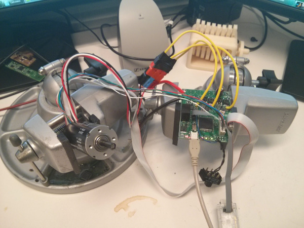
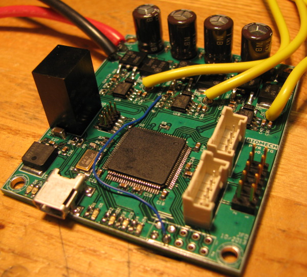
I decided to work on my brushless DC motor (BLDC) driver. I need this board both for my research and for my final project.
In Week 6 I introduced the project and showed a CAD rendering of the board. In Week 8
I mentioned some of the progress I had made. Although I soldered the power stage and I got the motor to spin in Week 9, I knew that
there was a mistake in my commutation table: it was possible to stall the motor and in one position it wouldn't start again without help.
This week I wanted to get that Maxon spinning fast and I wanted to play with some basic control loops.
Note: if you don't want the theory, you can jump right to the results. Here's a preview of what to expect:
I also did a lot of CAD for my final project.
What's a BLDC?
"Brushless DC electric motor (BLDC motors, BL motors) also known as electronically commutated motors (ECMs, EC motors) are synchronous motors
that are powered by a DC electric source via an integrated inverter/switching power supply, which produces an AC electric signal to drive the
motor. In this context, AC, alternating current, does not imply a sinusoidal waveform, but rather a bi-directional current with no restriction
on waveform. Additional sensors and electronics control the inverter output amplitude and waveform (and therefore percent of DC bus usage/efficiency)
and frequency (i.e. rotor speed).
The motor part of a brushless motor is often a permanent magnet synchronous motor, but can also be a switched reluctance motor, or induction motor.
Brushless motors may be described as stepper motors; however, the term stepper motor tends to be used for motors that are designed specifically to be
operated in a mode where they are frequently stopped with the rotor in a defined angular position."
Source: http://en.wikipedia.org/wiki/BLDC
The reason we call them "brushless" is because… well, they don't have brushes. Conventional DC motor need brushes to switch the polarity of the magnetic
field. No brushes, no rotation. (See that Wikipedia page for more information and animations:
http://en.wikipedia.org/wiki/Brushed_DC_electric_motor)
Brushed motor are extremely simple to drive. One simple needs a H-Bridge. The problem is the limited efficiency and the maintenance problems due to the
aging of the brushes. BLDC motor, although they need a more complicated driver, are now the standard in applications such as RC cars and planes, electric
vehicles and appliances.
"Brushless motors offer several advantages over brushed DC motors, including more torque per weight, more torque per watt (increased efficiency),
increased reliability, reduced noise, longer lifetime (no brush and commutator erosion), elimination of ionizing sparks from the commutator, and
overall reduction of electromagnetic interference (EMI). With no windings on the rotor, they are not subjected to centrifugal forces, and because
the windings are supported by the housing, they can be cooled by conduction, requiring no airflow inside the motor for cooling. This in turn means
that the motor's internals can be entirely enclosed and protected from dirt or other foreign matter."
Source: http://en.wikipedia.org/wiki/BLDC
One problem with BLDC motors is that the controller needs to know the position of the rotor to energize the proper phase. It's possible to use the
back-EMF ("sensorless" commutation) of the motor to estimate the shaft position but for that technique to be used the motor has to be turning (ie:
it's bad near 0 RPM). Otherwise you need sensors in the motor. A common thing is to have 3 Hall effect sensors placed 120 electrical degrees apart in
the motor. The rotor's position is decoded from the Hall output code. The link between the phases and the Hall code is usually done through a look-up table.
For more information about BLDC drivers, please refer to Microchip AN857
Implementation: fixing bugs and testing open-loop
The first thing was to debug the commutation table. I went over the Microchip App note and the Maxon datasheet multiple times; I couldn't find a
difference with my table and theirs. I started probing on the PCB, looking for my PWM signals and then I saw that on one phase, one of the high-side
gate resistor was only soldered on one side. That explained why I had a dead spot in my rotation.
I soldered the second terminal and it solved the problem. The motor didn't stall and had more torque. I wrote the other half of the table to deal with
negative rotations. At this point I could change the speed and direction of the motor on a terminal. I was ready to write a position controller.
Control loop basics
Now, let's look at the simplest controller possible, a bang-bang controller. It's used in all the old thermostats, in your oven and in (way to many)
appliances. In an oven, the element will be powered. The temperature will rise up to the set point. At this point, the controller will turn off the
element. As soon as the temperature gets below the set point, it turns on again. It's easy to imagine that the heating element might get switched really
fast around the threshold. To avoid that, designers will build hysteresis in the system. That way, your oven will go a couple degrees over the wanted
temperature, will turn off, wait for the temperature to drop a couple degrees below the set point, then turn on…
For an oven, that's OK. It's imperfect but it's dirt cheap and it does the job. Now think about your car's cruise control. Using a bang-bang controller
would mean slowing down, than pressing the pedal to the floor to get over the wanted speed, than releasing. Not what you want.
The easy fix is to measure the error and to act accordingly. If you are going at 25MPH and you want to get at 60MPH, then yes you will probably press
the pedal to the floor. But if you are at 58, a gentle push will get you at the right speed, without going over. That's a proportional controller.
That's a good solution that can work for simple problems. Depending on the gain it can be unstable or can leave a constant error. The common solution
is to complement it with Integral and Derivative terms and to build a PID.
PID
"A proportional-integral-derivative controller (PID controller) is a generic control loop feedback mechanism (controller) widely used in industrial
control systems. A PID controller calculates an "error" value as the difference between a measured process variable and a desired setpoint. The controller
attempts to minimize the error by adjusting the process control inputs."
Source: http://en.wikipedia.org/wiki/PID_controller
While it might sound complex (and it can be), keep in mind that using a basic PID controller is really simple.
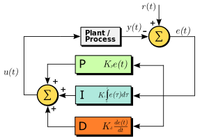
In our context, we use a fixed time base (1ms). e(t) is simply the error (error = wanted – actual). The integral of the error over time is a summation:
every cycle you add the actual error to the same variable. The differential error term is a simple subtraction: new error minus last error.
In front of those 3 error values are constants (Kx). They are the parameters that you can tweak to get the system response that you want.
Kp is probably the most important of the 3 parameters. It's the one with the most influence on the system's response. A higher Kp will lead to a
faster correction of the error. However, going too high can cause overshoot and instability. A small Kp can lead to a constant error (the controller
isn't strong enough to drive the error to 0).
Ki is used to remove the constant error of the proportional controller.
Kd is used to improve the stability of the loop and to improve the settling time. It's common not to use it because of its noise sensitivity.
This week I implemented a PI controller. I'll experiment with a filtered derivative term in the future to see if I can get better performances.
Implementing a position controller
For robotics application it's common to close a position loop around a motor. I wanted to try a simple PID position controller with the BLDC and its
integrated optical encoder.
I started by setting a hardware timer in my PSoC. I used 1ms as it's a common value for position controller. Every millisecond an interrupt fires.
In that interrupt service routine I read the encoder count and I lift a flag.
Here's my simple PI code:
//Global motor control variables
int16 old_enc_count = 0;
int16 new_enc_count = 0;
int16 diff_enc_count = 0;
uint8 motor_control_flag = 0;
//Position controller
#define POS_PWM_LIMIT 320 //10%
#define MAX_CUMULATIVE_ERROR 200
#define GAIN_P 3
#define GAIN_I 1
int16 sumoferrors = 0;
int16 error = 0;
int16 pwm = 0;
uint16 setpoint = 10000;
//Hold current motor position - v2 non blocking
void hold_motor_position2(int16 wanted_pos)
{
int16 p = 0, i = 0;
error = new_enc_count - wanted_pos; //Actual error
sumoferrors = sumoferrors + error; //Cumulative error
//Saturate cumulative error
if(sumoferrors >= MAX_CUMULATIVE_ERROR)
sumoferrors = MAX_CUMULATIVE_ERROR;
if(sumoferrors <= -MAX_CUMULATIVE_ERROR)
sumoferrors = -MAX_CUMULATIVE_ERROR;
//Proportional term
p = GAIN_P * error;
//Integral term
i = (GAIN_I * sumoferrors)/100;
//Output
pwm = -(p + i); //
//Saturates PWM to low values
if(pwm >= POS_PWM_LIMIT)
pwm = POS_PWM_LIMIT;
if(pwm <= -POS_PWM_LIMIT)
pwm = -POS_PWM_LIMIT;
motor_open_speed(pwm);
}
The main difference with this code and the PID explanation is the saturation of the summed error. It's sommon to saturate that variable to avoid
overvflow problems (and instable loops). It reduced the effect of the I term, but it still does what I want (removes the constant error).
The gain values were experimentally determined. I started with a Kp of 1 and a Ki of 0. The motor was holding a position. I increased Kp to 2 and
it started shaking around the wanted position. Adding a small Ki correction (0.02) removed the constant error and gave me a stable system.
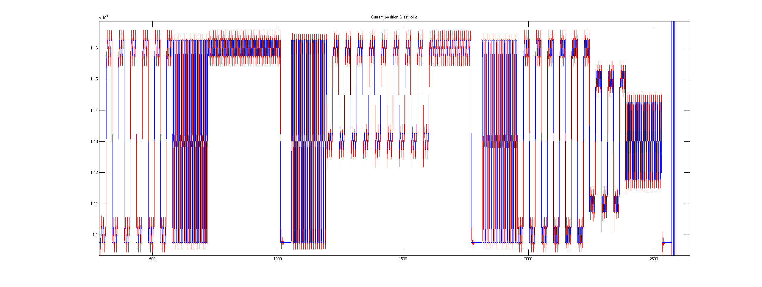
Here's the first Matlab plot that I got. Kp is 2 and Ki is 0.02. The data is sent to the PC every 25ms. That's a tradeoff value that allows me to
get graphs in real time but it's too slow to do a good analysis of the control loop. I'll need to change that.
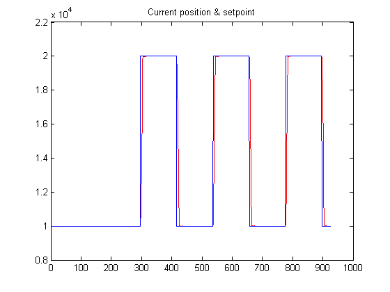
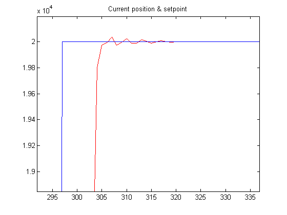
As you can see, the motor (red) is tracking the set point (blue). If I zoom you can see more details:
And here's the error plot for the same experiment:
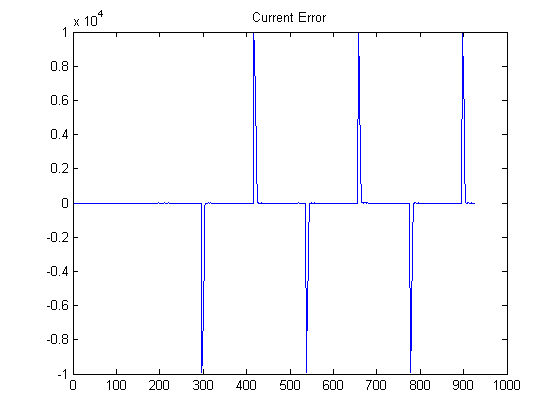
I successfully tracked saw-tooth signals. In fact it's much easier for the controller than to track step functions.
Demonstration
At this point I was happy with the state of my controller. There is no need to tune it more for now; it will have to happen with the real
setup. What I didn't like is the lack of a "wow" factor. What could I do to show the results of my position controller? I initially thought
of doing a persistence of vision (POV) display but I didn't really want to spend the time to build the LED circuit. Then I had a stupid idea:
why not write text with the motor? On all those Matlab plots the X axis is time and Y is position. If I raster in Y, I can use the same
persistence trick to display text.
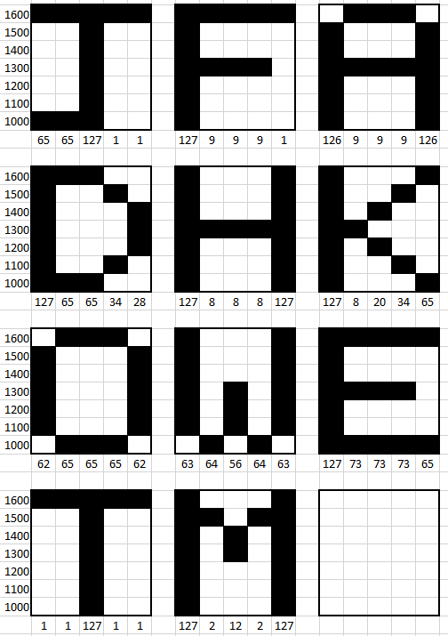
I won't go over the details, but if you are curious you can look at my ugly Matlab character generation function and text generation code.
And here's the result for the full text (I modified the code between printing 'JFD' and 'HOW TO MAKE'):
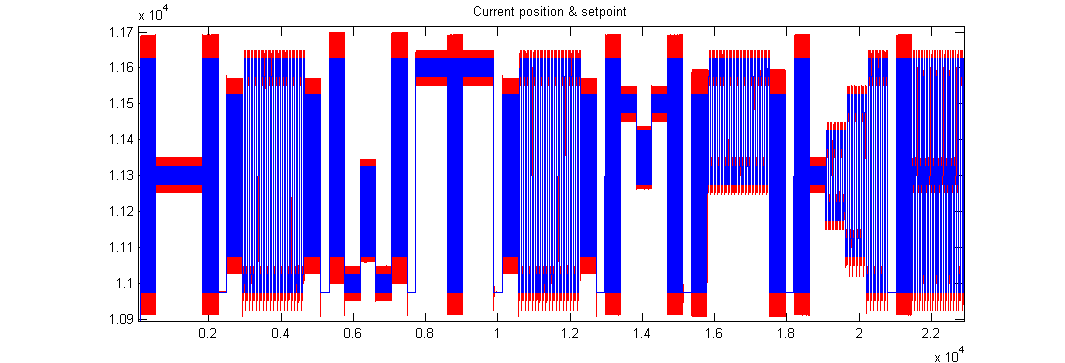
As you can see on the plots the motor can't perfectly track the set point but it doesn't really matter for that application.
For the sceptics: here's a video of the motor "writing" 'JFD'.
Final Project Update
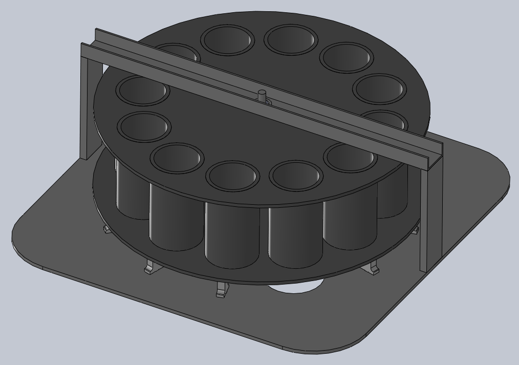
Last week I brainstormed about this project with Alex Robinson. He spent some time sketching his vision of the project. This week I CADed about 35% of the mechanisms.
Round chamber, viewed from the top (the loading side). Each cylinder can hold one glass.
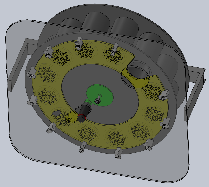
Bottom view with the aluminum plate transparent. You can see the Maxon BLDC motor (black and red), the gears (green) and the retaining plate (yellow). The retaining plate
has one big opening for the brush (on the top right corner) and one small opening for the unloading mechanism (bottom left corner). All the other small round holes are
for water to drip.
I also designed the first version of the outer shell and of the user interface.
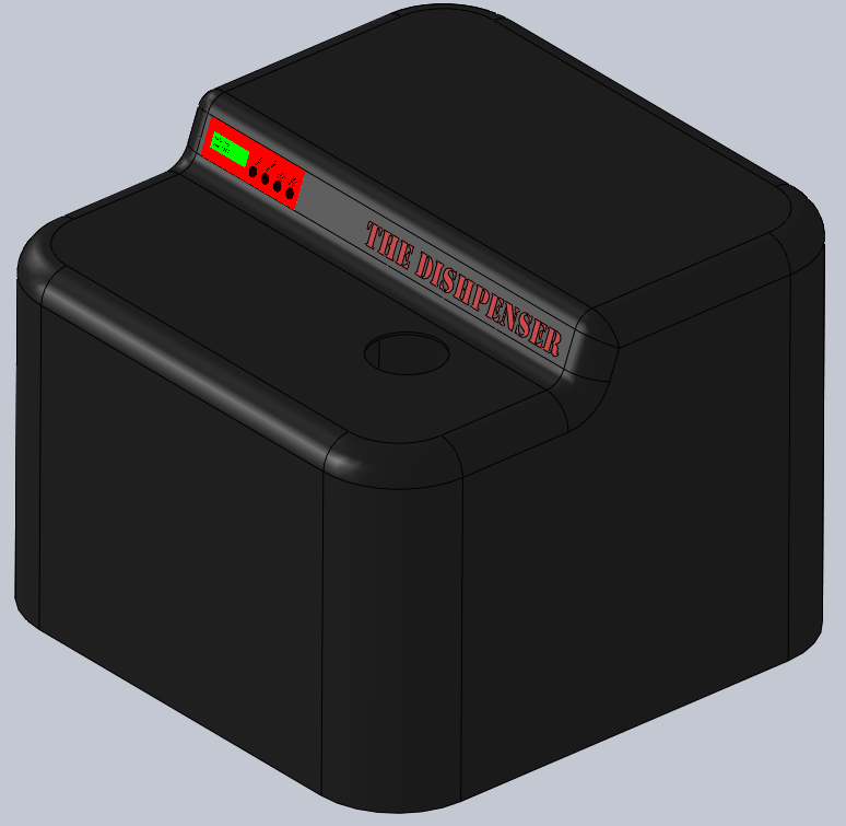
Hopefully this is ugly enough that Basheer will feel the need to give me a hand on the industrial design!


Jean-Francois (Jeff) Duval - jfduval(@)media(.)mit(.)edu - 2013
Top | MIT Media Lab | How To Make (almost) Anything 2013 | Index
"Hidden" keywords: Jean-François Duval, JFDuval, Jeff Duval, PCB, Dishpenser, MIT Media Lab, Biomechatronics, Electronics, Robotics, DIY, Hack, Hacker