Week 14: Final Project
Last week I described the electronics of the DishPenser. I ended my update with updated CAD renderings of the project and pictures of some of the elements.
Since last Wednesday I've been extremely busy on the mechanical design and fabrication. My goal was to do most of the mechanics this week, leaving me a week to tweak and program the system.
As of Tuesday 10pm, I can say that I was able to successfully test most of the systems. There is still a lot of work to do, but I made good progress.
Here's a log of my progress (and mistakes).
12/06/2013
I assembled the round chamber. Everything is held together with hot glue. I've been using a lot of hot glue this week to test the initial designs. Tip: to easily remove it, use high % alcohol (91% works fine).
I could manually turn it but the friction was high. The red holders were supposed to be in UHMW but to save time I ended up laser cutting them in acrylic. With a slight design change (reduced the contact surface
by increasing the fillet radius) I made it better.
Most of my day was spent CADing new parts and modifying existing ones.
12/07/2013
One big question was: is my Maxon BLDC able to move the round chamber? The biggest reduction ratio I could use with the gears I found was 1:4. With all the inertia and friction, I knew I didn't
have big margins. My parts were designed to easily accommodate a bigger gear, so at least I had a backup.
The first test was pretty hacky… I was holding the motor in one hand and with the other I was changing its speed through a serial terminal. At low PWM duty cycle (below 40%) nothing moved. When I
reached around 40%, the motor was making crazy noise – not something normal. I quickly found out that my power supply was sagging and that my board was quickly turning on and off.
I hooked my cable to a huge 40V 15A power supply that used to belong to MIT's Leg Lab. With this setup I made the round chamber spin. The motor needed 4A at 24V… not good for an unloaded barrel.
It was also quickly getting warm.
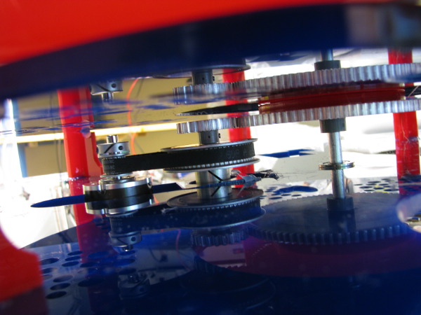
I did some calculation and there was no good way to get a good increase in the gear ratio. At max I could get a gain of 2. I decided to use two pulleys and a belt in addition to the original gears.
Reduction ratio: 1:16.
I laser cut some acrylic and I turned a steel shaft. It was impossible to support this shaft… but it was clear that it needed support as soon as I assembled the thing. The angular play was much
too high (although it looks OK on the following picture)
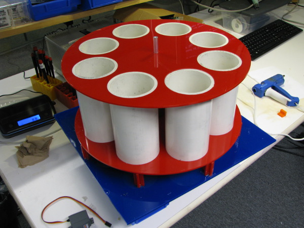
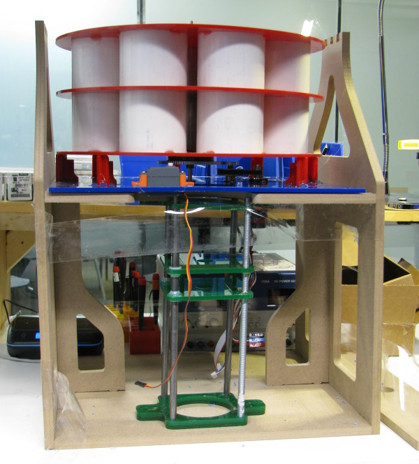
As I was getting more confident in the design of the round chamber, I decided to make it permanent. I removed all the hot glue and I cleaned the parts. I faced the PVC pipes on the lathe to get a
smoother surface. I reassembled everything (plus a new middle part) with epoxy. It's much sturdier now. It will help with my friction issue.

I assembled and tested a new version of the glass exit mechanism (I need something to push the glass up so the user can grab it). On the table, it's awesome. However, when assembled under the round
chamber, it's terrible. It needs a perfect alignment. Rather than redesigning a better version I decided to simplify the system by using the brush to do that function.
I spent a lot of time on the brushing mechanism. I needed to figure it out as soon as possible so I could design the frame. I needed the frame for the round chamber tests. That's the problem with a
design-try-fail-redesign process: you start prototyping parts without having your system fully designed. It speeds up considerably the process, but it implies that some parts might get redesigned
multiple times to accommodate new components.
12/08/2013
I redesigned the shaft and the plastic pieces to support a longer shaft with 2 bearings. Lots of small part only to hold a shaft, but it solved the problems.
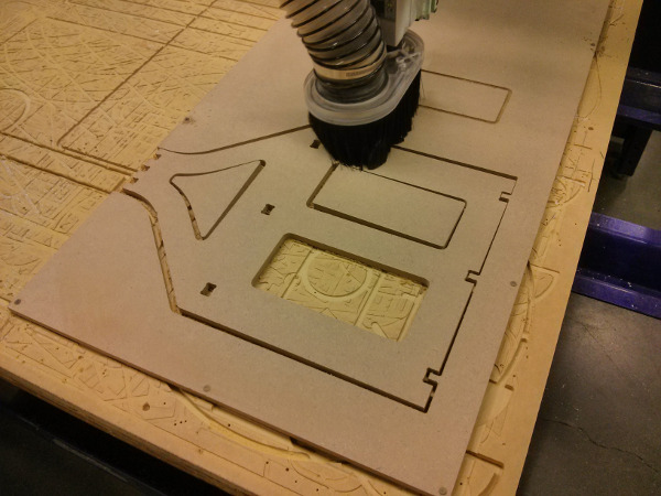
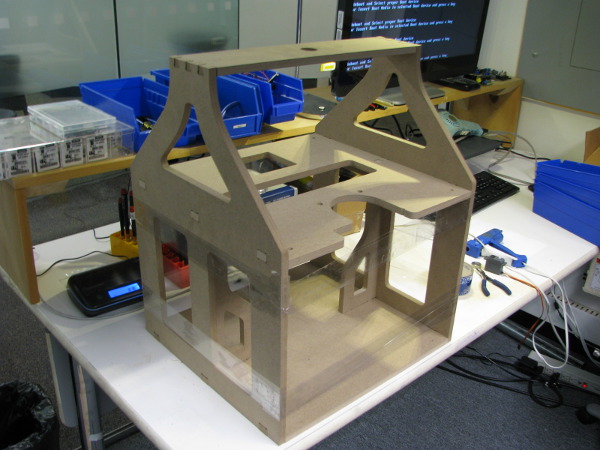
I used the ShopBot to machine the MDF frame.
I designed a preliminary brushing mechanism. It didn't include the motor mounts but I wanted to see if I could at least manually make it move. The answer is yes, I can move it.
But it's sloppy. When inserted in the MDF frame it's not too bad… but not great. To make it work, I assembled the whole thing and moved it up and down. When I was satisfied with the
motion I hot-glued the bushings and the acrylic parts in place.
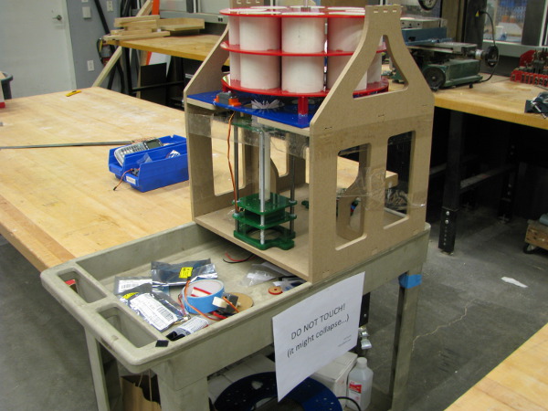
On the next picture you can see the DishPenser partially assembled for the first time.
I tested the servo mechanism that I designed to prevent the glasses from falling in the cleaning hole. It the one you can see on the previous picture. It doesn't work, the glass
drops and pushes the retaining arm open. So far, none of my servo mechanisms work…
12/09/2013
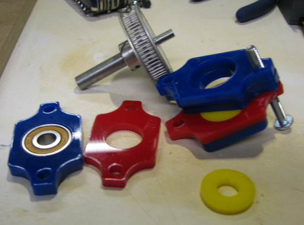
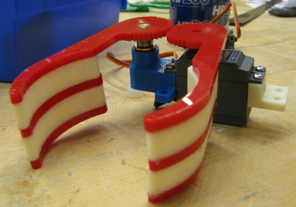
I need two things: a mechanism to prevent the glass from falling into the cleaning hole and a mechanism to clamp it while I brush. I decided to combine both function in one design:
a simple robot gripper. Sources of inspiration: Graboid, Lynxmotion. The gear models were downloaded from Boston Gears. I modified them to incorporate the holders and the mounts.
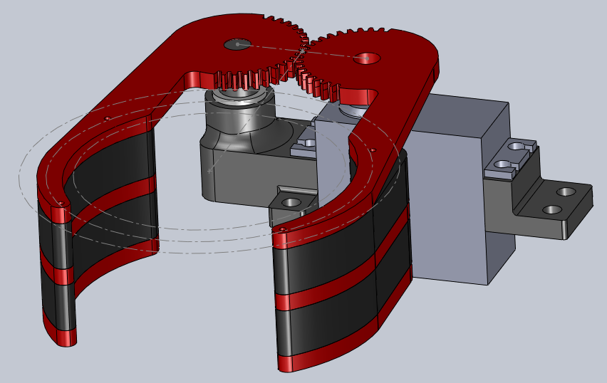
The red pieces are acrylic and the black pieces are 3D printed (ABS and PLA). The rendering is from the improved version, as the first one wasn't a success. I thought I supported
the free axle enough… but no. I also thought that I could turn such a short shaft without using the live spindle: turns out no. When I finally machined enough material off to fit
my bushing, it was way too slack.
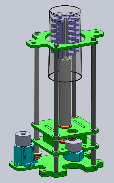
I spent many hours on the new version of the brushing mechanism: one that would be sturdier and that would include the 2 motors (one to spin the brush, one to move it up and down).
At the end of the day I laser cut new thick acrylic parts and I started a long 3D prints for the motor mounts.
12/10/2013
Today the goal was to make the brushing mechanism work and to assemble the new gripper. I moved all my parts to the shop and I started a long day of tuning and tweaking.
With the smaller hole size in the green plates, it was now possible to press-fit all the bearings and bushing. Awesome! No need for any glue.
I assembled the new brushing linear stage… and it didn't want to move. With my tighter tolerances I over constrained the design. I tried to smooth the rods with abrasive wool.
Better, but not enough. I increased the diameter of the holes in the bottom plates. Again, not enough.
At this point I consulted with Matt Carney. His advice was to over drill the bushing holes to allow
some motion. He also mentioned something that I knew but didn't fix: that the position of my threaded rod was wrong. Either it needs to be centered, or I need two.
As I made it work with slack holes earlier this week I decided to try it again. I increased all my diameters by 5%. I designed 3D printed bushing holders.
When reassembled, with screws and not glue, it worked! For sure it's still angled, but that's something that I won't fix today.
I moved on to the gripper design. On the next picture you can see the improved gripper version: more support from the 3D printed part and shorter unsupported
shaft. As a reference, the first shaft is the one on the table.
Here's the result:
End of day (and week) status:
Up to date CAD:
![]()
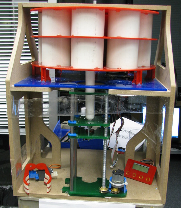
Picture of the DishPenser:
And a video of the brushing mechanism: http://youtu.be/2YpQGWgcR3c


Jean-Francois (Jeff) Duval - jfduval(@)media(.)mit(.)edu - 2013
Top | MIT Media Lab | How To Make (almost) Anything 2013 | Index
"Hidden" keywords: Jean-François Duval, JFDuval, Jeff Duval, PCB, Dishpenser, MIT Media Lab, Biomechatronics, Electronics, Robotics, DIY, Hack, Hacker