Week 12: Network and Communications
This week's assignment was to "design and build a wired &/or wireless network connecting at least two nodes."
This week I:
- Assembled and programmed an I2C Strain Gauge Amplifier
- Linked two boards with RS-485
- Completed my LED lamp project
- Worked on my final project
I2C Strain Gauge Amplifier
Arguably, the most common force sensor is the strain gauge . It's usually wired as a Wheatsone bridge:
2 wires for power, 2 wires for sensing. The differential voltage variation with strain is always small. The unit I'm using for this test is rated for 10kg and its gain is 1.7±0.03mV/V. If I power it at 5V, at full scale I'll
get 8.5mV. The output is referenced to half the supply voltage: the output of this sensor will be from 2.4915 to 2.5085V. To use the full input span of my ADC, I need a differential gain of ~300.
Strain gauge (or load cells) signal conditioners are always expensive. We are talking hundreds of dollars here. And it's nothing fancy, just a differential amplifier and some adjustment (offset and gain). As they
are mostly used for industrial applications, they are bulky.
In robotics it's common to integrate the amplifier circuit in a bigger design to save money and space. However, it's still too common to see bad circuits that are extremely noisy and/or marginally stable. With 2
applications in mind (my BLDC motor driver and the FitSocket) I designed a small circuit that should get rid of the typical problems.
Other than being careful with the analog design, the twist I'm adding is I2C programmable gain and offset. The result can be read through I2C (12bits) or can be read as an analog voltage. Having programmable offset
and gain means that you will never have to adjust the potentiometers on every board before an experiment. This will be particularly useful for a project like the FitSocket that has 14 amplifiers:
Strain Amp v0.1:
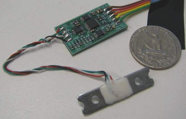
Please note that this is a first prototype, intended to test the concept and the analog circuitry. The next version will use 0402 passives and a PIC24 instead of the I2C amplifier. It will be smaller and I'll have a single I2C
address per sensor (right now I have one for the digital potentiometer and one for the ADC. I'm limited to 9 slaves.)
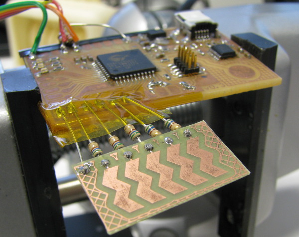
I wired the Strain Amp to one of my PSoC v0.3 boards:
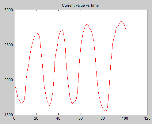
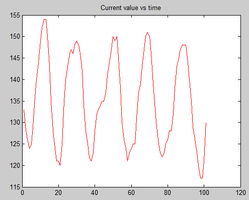
I wrote some C code to program the digital potentiometer and read the ADC by I2C. Testing at 3.3V (only 66% of the maximum gain) I was able to cover the full voltage span. The static noise is below ±1%. Adding a
60Hz notch filter should further reduce that number. I'm currently sending the data over USB (serial over USB) to be displayed in Matlab. Here's a meaningless graph (I was pressing on the gauge with my finger):
RS-485
For my research I will need, amongst many other things, to link a robotics knee with a robotics ankle. Although EtherCAT would be perfect for that (high-speed, high noise immunity, hot-pluggable, …),
I decided to do a first proof of concept with RS-485. It is much cheaper and much simpler. Who knows, it might be enough for our needs? Otherwise, my modular design approach will allow me to change the
communication layer later on.
I'm using Analog Devices ADM4850 transceivers. Why this one? Biomechatronics has
more than 30 of them in stock. It's a slow transceiver, only 115200 bps, but it will do for a first try. On my next Digikey order I'll get some
TI SN65HVD78 transceivers (TSSOP-8, 3.3V, 50Mbps).
I used some Sparkfun SOIC-8 to DIP-8 adapters to test the chips. I wired one transceiver to the same PSoC 0.3 board that has the strain gauge and one to the BLDC driver board. The link between the two
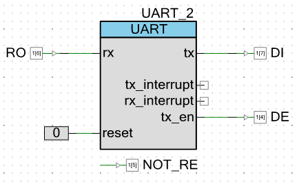
is a 20cm long twisted pair. In PSoC Creator I'm using a UART_v2_30 UDB module. It has a TX_EN pin that goes high when it's transmitting. Other than that, it's similar to any UART. You write one byte to a
register and it's sent. I'm dealing with the Receive Enable (RE) pin in software.
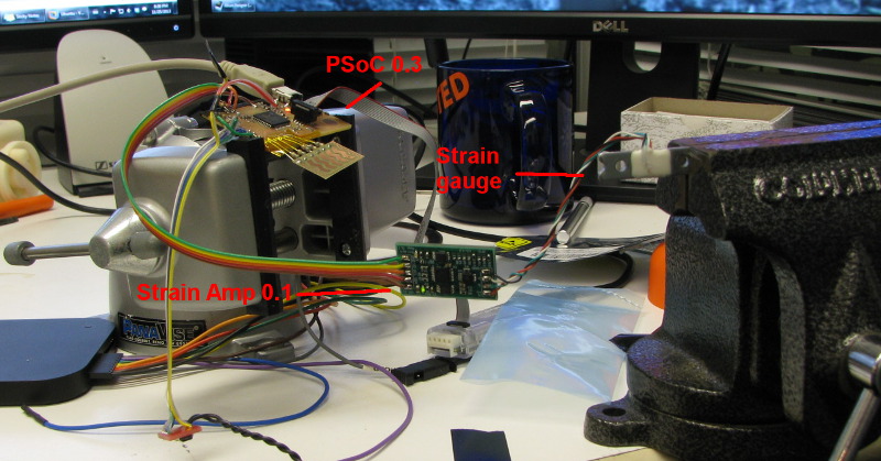
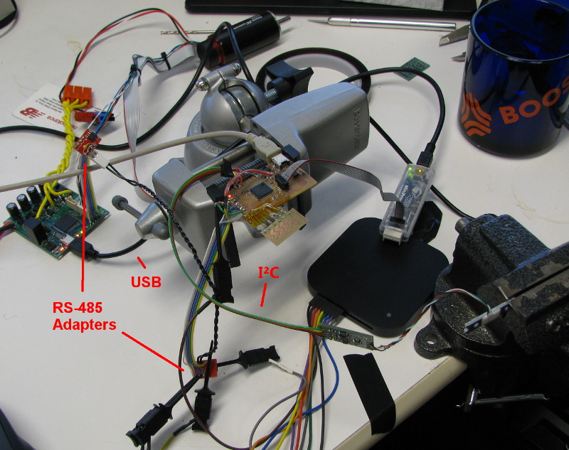
For now, I'm sending a single byte from the PSoC 4 (always a Master (sender)) to the PSoC 5 (always a Slave (receiver)). The byte I'm sending is a 8 bits version of the measured strain. The system is then:
[Strain Amp 0.1] <==> I2C <==> [PSoC 4 0.3] ==> RS-485 ==> [PSoC 5 BLDC driver] <==> USB CDC <==> [PC running Matlab]
Here's the setup and another meaningless graph showing the results:
Soon I'll experiment with a modified MODBUS protocol and with multi-drop.
LED Lamp: completed
As I'm starting to feel the end of semester pressure I want to complete as many projects as possible. I started my LED lamp on Week 7 and worked on it in Week 8
Even though I would love to push this project further (and I might do it, but not this semester) I decided to quickly wrap-it up.
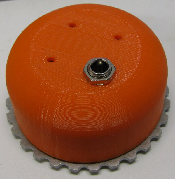
As I wasn't satisfied with the quality of the casted part I 3D printed a new cover on the MakerBot. It took only an hour and the result isn't bad at all. Casting is the way to go for when I'll want many lamps,
but for now 3D printing is much less time and energy consuming.
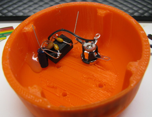
To power the electronics I need a DC voltage from 3 to 5V. My wall adapter is 18V. I went the easy way and I bought an integrated 5V SMPS (CUI V7805-500). I wired it using the "dead-bug" technique (also known as "point-to-point construction").
To control the brightness my plan has always been to use a capacitive slider. I was planning on making it with the vinyl cutter up to last week. When shopping on Digikey for FR-4 copper clad I found some 1/64 boards.
They are quite flexible!
I etched a small slider and I wired it to my PSoC dev board to try it. I can easily detect the presence of absence of a finger and can get an accurate centroid. The default CapSense configuration gives you a centroid between
0 and 100: more than enough for this application.
My first attempt was to hot glue the small PCB to the enclosure. The heat made the PLA flexible and it bubbled… not good for a capacitive sensor (you want the finger to be at a constant distance from the sensor in the Z axis).
It also wasn't strong enough to hold the PCB against the curvy surface. I reworked the enclosure with a heat gun to remove the bubble and I used epoxy to glue my board.
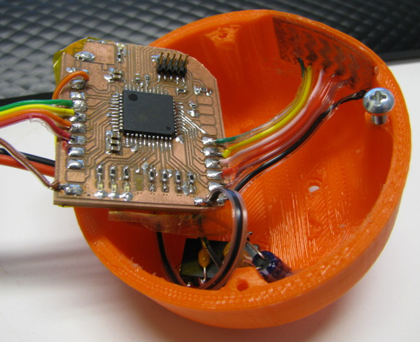
The PSoC dev board that I had was too big for the enclosure. I used the band saw to remove the capacitive button and the USB-Serial circuitry. I sanded the edges round. Hacky, but it works. I wired the LED driver board
and the new capacitive slider to the PSoC:
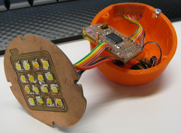
I laser cut a piece of thermal transfer pad and assembled the final unit:
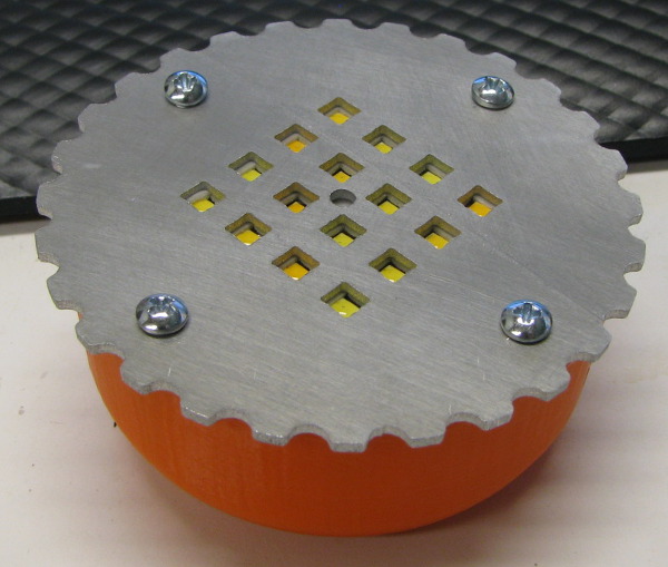
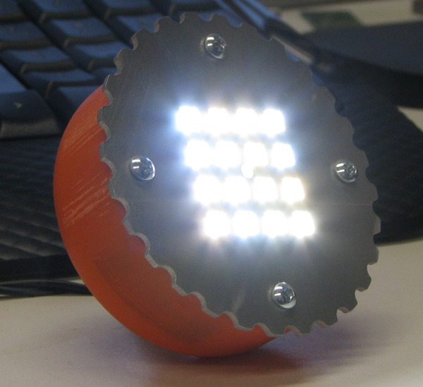
It's really bright! It's really bright! You can change the brightness from "off" to "pretending to be the sun" by sliding your finger on one side of the enclosure.
I have plenty of ideas to make it better, but for now it has reached the "good enough" point. LED lamp: completed.
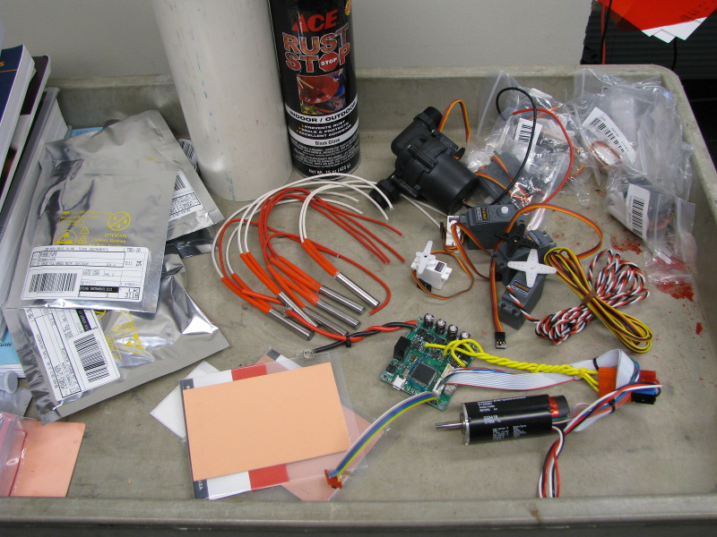
Final project update
The last couple weeks I've been buying materials and parts for the final project. I now have an interesting collection of items ready to be modified and integrated in the project: servos, water pump, heating elements,
1 and 2oz copper clad, IC samples, wire, tubing, etc.
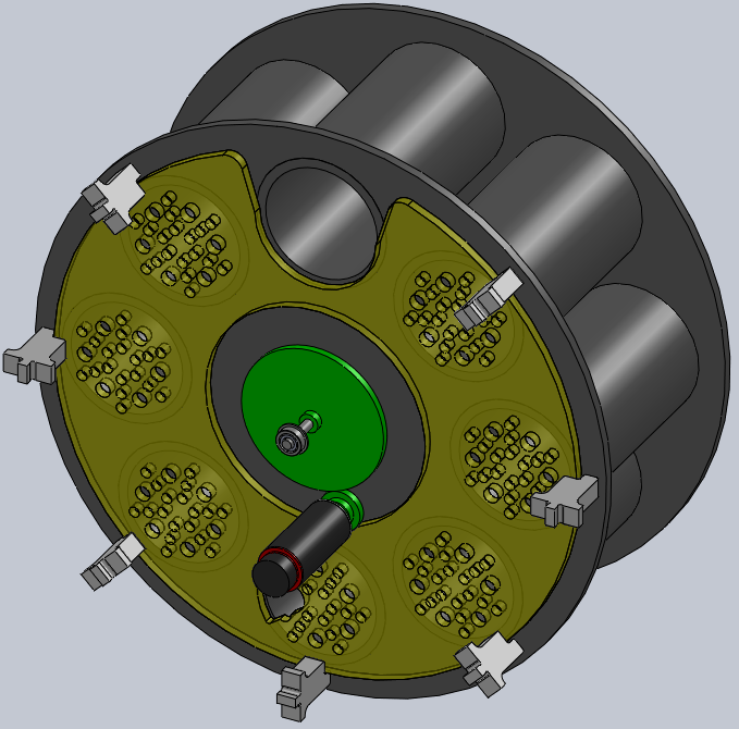
While looking in stores and in the fab inventory for construction materials like plastics and metal I realized that this project was physically too big for no good reason. By reducing the glass count from 12 to 8 I
can use the plastic sheets that we have in stock and metal will be cheaper. The lower weight will reduce the mechanical stress on my other components. And it will fit better on my counter top.
I modified my CAD:
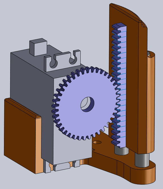
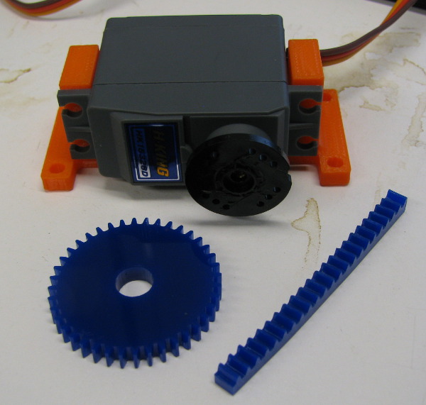
I also started designing and building small mechanisms. This is the mechanism that will allow the glasses to be taken out. The sprocket and rack are laser cut.


Jean-Francois (Jeff) Duval - jfduval(@)media(.)mit(.)edu - 2013
Top | MIT Media Lab | How To Make (almost) Anything 2013 | Index
"Hidden" keywords: Jean-François Duval, JFDuval, Jeff Duval, PCB, Dishpenser, MIT Media Lab, Biomechatronics, Electronics, Robotics, DIY, Hack, Hacker