Week 15: Final Project
12/11/2013
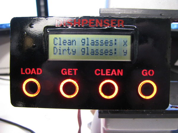
Designed a simple case for the UI. I then programmed the UI with common actions and I assembled it. I succeded at offering feedback through the use of LEDs.
I forgot to take pictures at this point, but if you scroll down you'll see the final UI.
Soldered 90% of the brushed DC motor driver.
I started writing down a communication protocol. I defined constants and fixed the network architecture. I ran some tests on the RS-485 network I had between
two of my boards from a past week. It didn't work, my dev board was causing a USB reset… not good. I couldn't see anything wrong on the board but I couldn't get
it to work. I tested between the servo board and the BLDC driver and it was fine, I could send strings of data over RS-485. I later found out that this particular
USB cable had an internal short.
12/12/2013
As mentioned before, on the Servo board I used a PSoC 4100 instead of a PSoC 4200. Whithout UDBs this board would have required different code than all the other
boards so I went ahead and replaced the TQFP-44 chip.
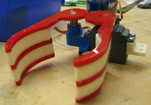
One of the big unknowns is the gripper. Will it work better than the simple mechanism that I discarded before? The first test was to write some code to control it.
As you can see in this video (if you click on the picture) it's working.
I wasn't in the mood to redesign once more the glass retaining/gripping/clamping mechanism so instead I programmed the DC motor board. I fought for half an hour with
the truth table; it seems I didn't get how to use the MODE1 pin right the first time. I flipped a bit and everything started to work: I could control the speed and
direction of the Jameco gearmotor.
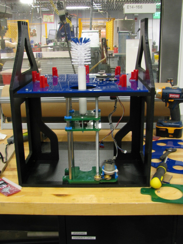
I wrote some code to test the ultrasonic range finder that I obtained from Object based Media. With the sensor taped in the frame my code measured 277mm between my MDF
plates. The real distance is 298 mm, but if you subtract 25mm (sensor's height) it's spot on. Good, I now have a way to know the position of the brush.
I consulted Felix Heibeck and Basheer Tome about the appearance of my project. Like most engineers, I waited until 95% of the product was done to ask the industrial
designer how I could make it look good… They gave me some good advice about paint and clear acrylic casings.
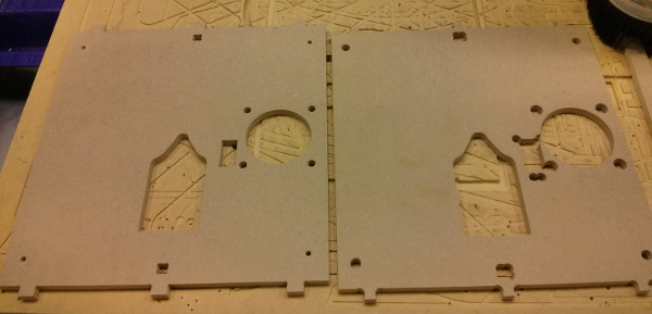
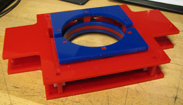
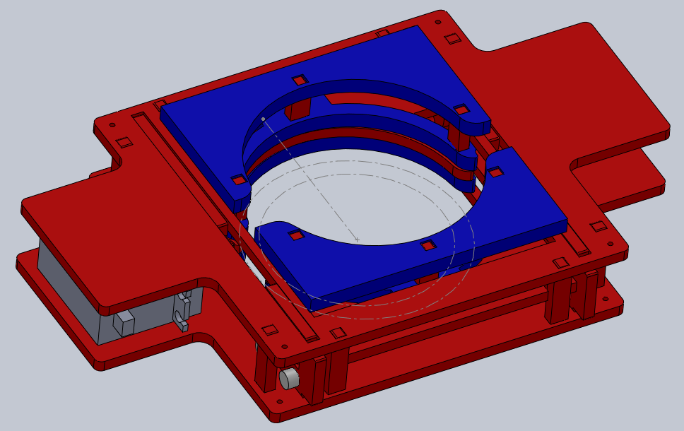
I redesigned some of the Round Chamber parts: blue plate, blue retainer, gliders. I laser cut some of them.
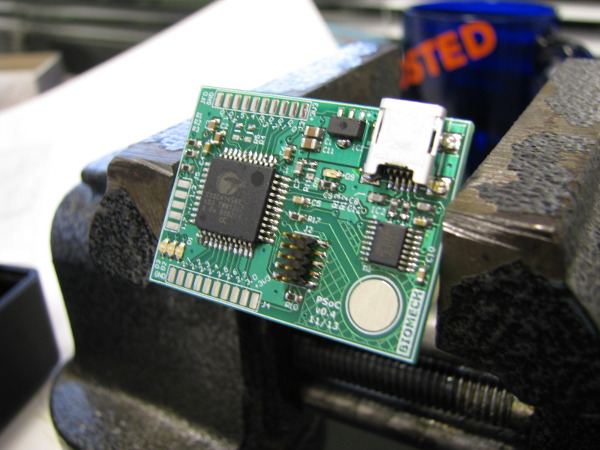
I assembled a new PCB: PSoC 4 dev 0.4. That's a professionally made version of the dev board that I developed in an earlier week.
12/13/2013
I went to Home Depot to get more MDF, spray paint and screws.
I laser cut the new gliders that I designed yesterday.
I used the big Shopbot to cut two of the frame pieces that were redesigned. I didn't realize that the "cut on line" option was checked. It made all the holes way too big.
I had to re-cut the two parts.
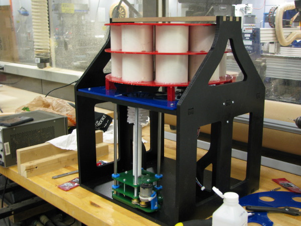
Following my designer's advice I painted the frame black.
I reassembled the DishPenser.
I did a manual gripper test in the assembly. Things didn't go well. My glasses have a small lip that easily gets caught. I need a "good transition" between the retaining
ring (the big blue ring with lots of holes) and the glass retaining mechanism and that's not something I can get with this gripper.
After talking with Arthur Petron about the issues we concluded that the only way to resolve it was to design a parallel mechanism. That's something I had been avoiding,
fearing the complexity. Not that I had no choice I started CADing it.
12/14/13
Worked on the parallel gripper: first version didn't slide at all. Way too much friction.
Second version with white pegs as gliders: much better, but not quite there.
Modified the version with pegs, made it. Took me a solid 12h to get to this point
12/15/2013
Some setscrews got loose. I added lock tite. One belt needs to be changed.
MiniProg3 (PSoC programmer + debugger) problem, can't program the BLDC driver… but the PSoC 4 boards are fine. Can't see a good reason why. I played with the options:
with the Power Cycle acquisition mode I can flash my chip, but I can't debug and it takes forever.
Changed the belt brush. I made sure that it was well tensioned to avoid damaging it. Working.
Wrote PI code for ultrasound + brush, working.
Filmed demo of 3 positions (click on the picture for the video):
Felix designed and made a vinyl overlay for the UI. I applied it. It looks really good!
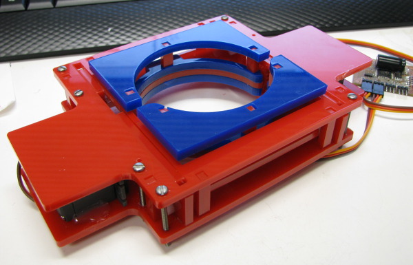
Assembled the parallel gripper. (click on the picture for a video.
12/16/2013
I called Cypress technical support. The engineer suspected a bad reset line. She was right, it seems that one of my via was broken… but it was working before. Did 4PCB
leave some acid in there? Did I destroy it while handling the board (power surge, really bad ESD discharge?) No one will know, but it works with a jumper.
My day was spent making the project pretty, taking pictures, documenting and writing software. That last part didn't go as well as planned. It's hard to debug a
system when all the sub systems are barely tested. I kept running into stupid bugs. At the end, I have a simplistic demonstration. Nowhere near what I wanted to show the world.
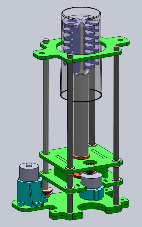
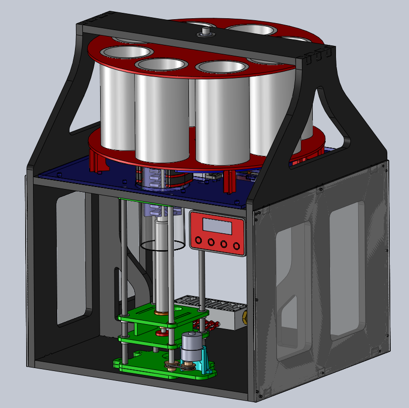
Click on the rendering for the last video: the first integration test.
12/17/2013
After lots of sleep (a whole 2h!) I was determined to get the round chamber moving again. I fixed the mistakes in the position controller code and I linked the BLDC driver and the UI board through RS-485.
I cleaned the cables and wired the power supplies. The DishPenser is now ready for the evaluation and the open house.
Click here for the final video.
For more details and pictures, please refer to the DishPensher page.


Jean-Francois (Jeff) Duval - jfduval(@)media(.)mit(.)edu - 2013
Top | MIT Media Lab | How To Make (almost) Anything 2013 | Index
"Hidden" keywords: Jean-François Duval, JFDuval, Jeff Duval, PCB, Dishpenser, MIT Media Lab, Biomechatronics, Electronics, Robotics, DIY, Hack, Hacker