Week 6: Electronics Design
This week's assignment was to "redraw the echo hello-world board, add (at least) a button and LED (with current-limiting resistor), check the design rules, and make it".
As stated in my Week 3 page, I started using Cypress Programmable System on Chip (PSoC) controllers
for this class and for my research projects. At the beginning of this month I designed and fabricated my first PSoC 4 development board. In the last 10 days I spent a lot of
time designing a PSoC 5 based brushless DC (BLDC) motor controller and a second version of my PSoC 4 development board.
The next sections will talk about the PSoC chips, my custom dev boards and my BLDC driver.
Cypress Programmable System on Chip (PSoC)
"PSoC is the world's only programmable embedded system-on-chip integrating high-performance analog, PLD-based programmable logic, memory and a microcontroller on a single chip."
(Source: http://www.cypress.com/psoc/)
This is not a pure microcontroller. This is not a CPLD or a FPGA. This is not a field-programmable array (FPAA). This is a mix of all these different systems in a single chip.
The PSoC 4 family is built around an ARM Cortex-M0 CPU. The chip I'm using for the dev boards, the CY8C4245AXI-483, costs 2$ (1k) and has:
- 48 MHz ARM Cortex-M0 CPU with single cycle multiply
- 32 kB of flash, 4 kB of SRAM
- Works from 1.71 to 5.5V. 5V modern microcontrollers are rare but can be really useful (in some design, you can get rid of the 3V3 regulator and have a single supply rail)
- Two opamps
- 12-bit 1 Msps SAR ADC with differential and single-ended modes
- Two current DACs (IDACs) for general-purpose or capacitive sensing applications on any pin
- Four programmable logic blocks, each with 8 Macrocells and data path (called universal digital blocks, UDBs)
- Two independent run-time reconfigurable Serial Communication Blocks (SCBs) with re-configurable I2C, SPI, or UART functionality
- Four 16-bit Timer/Counter Pulse-Width Modulator (TCPWM) blocks
- 36 GPIOs. Any GPIO Pin can be CapSense, LCD, Analog, or Digital. Drive modes, strengths, and slew rates are programmable
- Easy to use TQFP44 package or small 40 pins QFN
- And much more…
The PSoC 5LP (CY8C5868AXI-LP035) I chose for my BLDC driver is a monster… while it’s more expansive (11.88$ @ 1k) than the PSoC 4, it packs a lot more:
- 32-bit ARM Cortex-M3 CPU core, DC to 67MHz
- 256 kB of flash, 64 kB of SRAM, 2kB of EEPROM
- 24-channel direct memory access (DMA)
- Wide operating voltage range: 0.5 V to 5.5 V (including a high-efficiency boost regulator from 0.5 V input to 1.8 V to 5.0 V output)
- 72 I/Os (62 GPIOs, 8 SIOs, 2 USBIOs). Any GPIO to any digital or analog peripheral routability. 4 voltage domains for the IOs.
- 24 programmable logic device (PLD) based universal digital blocks (UDBs)
- Full CAN 2.0b 16 RX, 8 TX buffers
- 67-MHz, 24-bit fixed point digital filter block (DFB) to implement finite impulse response (FIR) and infinite impulse response (IIR) filters
- Configurable delta-sigma ADC with 8- to 20-bit resolution (up to 192 ksps at 12 bits or 48 ksps at 16 bits)
- Two SAR ADCs, each 12-bit at 1 Msps
- Four 8-bit 8 Msps current IDACs or 1-Msps voltage VDACs
- Four comparators with 95-ns response time, four uncommitted opamps
- Four configurable multifunction analog blocks. Example configurations are programmable gain amplifier (PGA), transimpedance amplifier (TIA), mixer, and sample and hold
- TQFP-100 or VQFN-68 packages
- And much more…
Listing all the features would require me to copy the entire datasheet in this page. This is not the goal. So, in terms of system integration, what can you gain from using a PSoC?
- With the 4 different IO voltage domains you can save on level shifters. Operating the system at 5V can allow you to save on one 3V3 regulator.
- Onboard USB: no need for an FTDI USB to Serial converter. And it’s faster (12Mbps).
- Some of the typical analog signal processing can be done with the digital filter block (DFB).
- Motor control features: complete hardware PWM generators, digital blocks to read the optical and Hall encoders, hardware look-up tables to cycle through output states, comparators for safety, …
- The Delta-Sigma ADC is perfect for sensors like load cells
- With the integrated opamps, comparators and filters you can easily build your SMPS driver in the PSoC, avoiding an IC
On the software side, everything can be done through the free PSoC Creator 3.0 IDE. It’s also possible to use 3rd party ARM tool suites (like Keil or IAR).
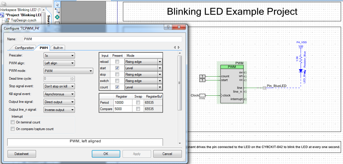
It’s possible to program the chip with a graphical user interface: you drag modules and you link them together with virtual wires. At Build time, those modules
are converted in hardware connections and C code. Here’s a screen shot of the Pioneer 4 LED blinker demo project (with the PWM configuration GUI open):
It’s important to note that you can do everything in pure C if you want. So far, using a mix of blocks + C has allowed me to prototype systems in a few minutes.
Much faster than having to go deep in the datasheet when all I want is to quickly test a sensor!
After 10 years of using almost exclusively Microchip MCU (PIC18, PIC24, dsPIC30F, dsPIC33F, dsPIC33E and PIC32) for projects and work, I must say that the PSoC are
quite refreshing. Yes, many MCUs are more powerful than PICs, but more computing horsepower is not always what you need to design a better system. Having reconfigurable
hardware is extremely useful, especially when it’s that cheap and easy to use.
PSoC 4 Development board
Software(s): Altium Designer 13 (ECAD), Solidworks (MCAD, for the component libs), PSoC Creator 3.0
The first version was minimalist:
- PSoC 4 (CY8C4245AXI-483) - ARM Cortex-M0 with digital and analog reconfigurable blocks
- USB (power only)
- SWD programming connector
- 3 LEDs
- Expansion connectors
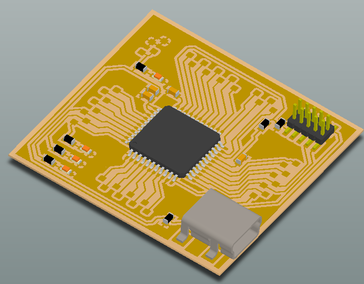
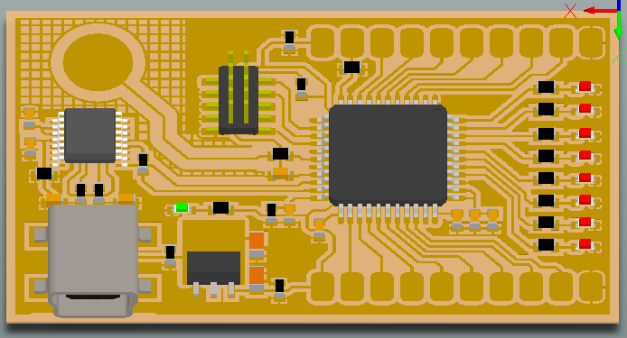
Yet, it allowed me to test the PSoC 4. I modified some of the Pioneer 4 example code and ran them on my board. I quickly realized that my design was not robust enough for the low-quality FR1 PCBs: the expansion pads are extremely easy to rip off. This is why on the picture you can see white tape holding all the wires and the board on my desk. Willing to test more peripherals and code on these awesome chips, I designed a second version of the development board. This one has more features:
- PSoC 4 (CY8C4245AXI-483) - ARM Cortex-M0 with digital and analog reconfigurable blocks
- USB: power and communication (through an FTDI FT230X USB to Serial converter)
- SWD programming connector
- 1 power indicator LED, 8 user LEDs on GPIOs
- 1 built-in capacitive touch sensor
- 2x 8 bits expansion connectors (with much bigger pads)
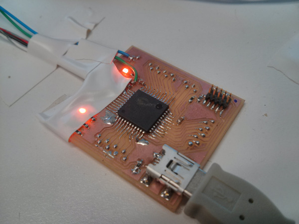
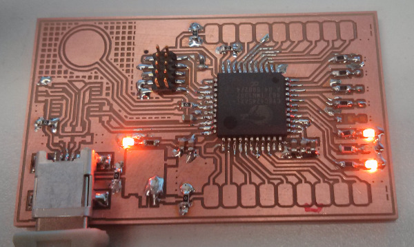
On the following picture you can see the actual state of the PCB. Note that some components are missing, as I’m waiting for my Digikey order. I assembled the core components with the
leftovers from v0.1. The board is currently programmed as a binary counter. When you tap your finger on the capacitive sensor, the count increases.
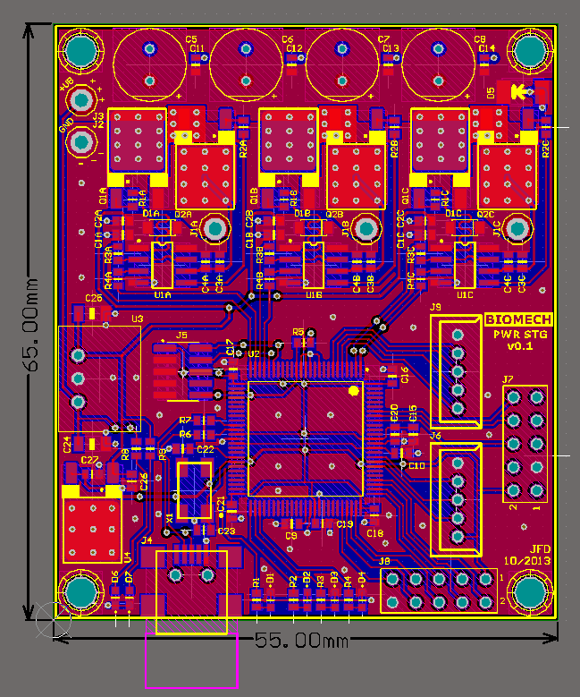
PSoC 5 BDLC Test Board
Software(s): Altium Designer 13 (ECAD), Solidworks (MCAD, for the component libs), PSoC Creator 3.0
I've developed multiple BLDC drive over the last 5 years. They all had one point in common: they were based on a Microchip dsPIC. These MCU are extremely common in motor control
application (and many other fields). They are handy chip with good capabilities. However, for this new design I opted for a PSoC 5LP. Doing so is a good way to avoid IP problems:
I have no other choice but to start from scratch. It's also a good occasion to try these chips. On that design I'll use a lot of the available peripherals. If things go as planned,
I'll be able to have a working design much faster than with a "conventional" MCU approach. This board also has the potential to be smaller and more integrated for less or equal money.
v0.1 is far from being complete. On purpose I kept the system as simple as possible. The goal here is to do BLDC commutation with the PSoC, and to test some of the peripherals. There is enough
hardware on this board to make a sensored BLDC motor spin.
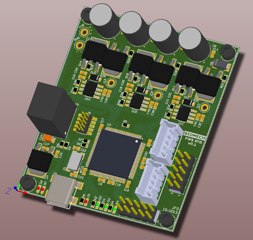
I'll receive the PCBs at the end of the week. More details to come.


Jean-Francois (Jeff) Duval - jfduval(@)media(.)mit(.)edu - 2013
Top | MIT Media Lab | How To Make (almost) Anything 2013 | Index
"Hidden" keywords: Jean-François Duval, JFDuval, Jeff Duval, PCB, Dishpenser, MIT Media Lab, Biomechatronics, Electronics, Robotics, DIY, Hack, Hacker