Embedded Programming
Programing with .c and ,make
To program my board, I use the hello.ftdi.44.echo.c file (first block) and hello.ftdi.44.echo.c.make (2nd block) as template.
// hello.ftdi.44.echo.c
//
// 115200 baud FTDI character echo, with flash string
//
// set lfuse to 0x7E for 20 MHz xtal
//
// Neil Gershenfeld
// 12/8/10
//
// (c) Massachusetts Institute of Technology 2010
// Permission granted for experimental and personal use;
// license for commercial sale available from MIT.
//

#include <avr/io.h>
#include <util/delay.h>
#include <avr/pgmspace.h>

#define output(directions,pin) (directions |= pin) // set port direction for output
#define set(port,pin) (port |= pin) // set port pin
#define clear(port,pin) (port &= (~pin)) // clear port pin
#define pin_test(pins,pin) (pins & pin) // test for port pin
#define bit_test(byte,bit) (byte & (1 << bit)) // test for bit set
#define bit_delay_time 8.5 // bit delay for 115200 with overhead
#define bit_delay() _delay_us(bit_delay_time) // RS232 bit delay
#define half_bit_delay() _delay_us(bit_delay_time/2) // RS232 half bit delay
#define char_delay() _delay_ms(10) // char delay

#define serial_port PORTA
#define serial_direction DDRA
#define serial_pins PINA
#define serial_pin_in (1 << PA0)
#define serial_pin_out (1 << PA1)

#define max_buffer 25

void get_char(volatile unsigned char *pins, unsigned char pin, char *rxbyte) {
   //
   // read character into rxbyte on pins pin
   //    assumes line driver (inverts bits)
   //
   *rxbyte = 0;
   while (pin_test(*pins,pin))
      //
      // wait for start bit
      //
      ;
   //
   // delay to middle of first data bit
   //
   half_bit_delay();
   bit_delay();
   //
   // unrolled loop to read data bits
   //
   if pin_test(*pins,pin)
      *rxbyte |= (1 << 0);
   else
      *rxbyte |= (0 << 0);
   bit_delay();
   if pin_test(*pins,pin)
      *rxbyte |= (1 << 1);
   else
      *rxbyte |= (0 << 1);
   bit_delay();
   if pin_test(*pins,pin)
      *rxbyte |= (1 << 2);
   else
      *rxbyte |= (0 << 2);
   bit_delay();
   if pin_test(*pins,pin)
      *rxbyte |= (1 << 3);
   else
      *rxbyte |= (0 << 3);
   bit_delay();
   if pin_test(*pins,pin)
      *rxbyte |= (1 << 4);
   else
      *rxbyte |= (0 << 4);
   bit_delay();
   if pin_test(*pins,pin)
      *rxbyte |= (1 << 5);
   else
      *rxbyte |= (0 << 5);
   bit_delay();
   if pin_test(*pins,pin)
      *rxbyte |= (1 << 6);
   else
      *rxbyte |= (0 << 6);
   bit_delay();
   if pin_test(*pins,pin)
      *rxbyte |= (1 << 7);
   else
      *rxbyte |= (0 << 7);
   //
   // wait for stop bit
   //
   bit_delay();
   half_bit_delay();
   }

void put_char(volatile unsigned char *port, unsigned char pin, char txchar) {
   //
   // send character in txchar on port pin
   //    assumes line driver (inverts bits)
   //
   // start bit
   //
   clear(*port,pin);
   bit_delay();
   //
   // unrolled loop to write data bits
   //
   if bit_test(txchar,0)
      set(*port,pin);
   else
      clear(*port,pin);
   bit_delay();
   if bit_test(txchar,1)
      set(*port,pin);
   else
      clear(*port,pin);
   bit_delay();
   if bit_test(txchar,2)
      set(*port,pin);
   else
      clear(*port,pin);
   bit_delay();
   if bit_test(txchar,3)
      set(*port,pin);
   else
      clear(*port,pin);
   bit_delay();
   if bit_test(txchar,4)
      set(*port,pin);
   else
      clear(*port,pin);
   bit_delay();
   if bit_test(txchar,5)
      set(*port,pin);
   else
      clear(*port,pin);
   bit_delay();
   if bit_test(txchar,6)
      set(*port,pin);
   else
      clear(*port,pin);
   bit_delay();
   if bit_test(txchar,7)
      set(*port,pin);
   else
      clear(*port,pin);
   bit_delay();
   //
   // stop bit
   //
   set(*port,pin);
   bit_delay();
   //
   // char delay
   //
   bit_delay();
   }

void put_string(volatile unsigned char *port, unsigned char pin, char *str) {
   //
   // print a null-terminated string
   //
   static int index;
   index = 0;
   do {
      put_char(port, pin, str[index]);
      ++index;
      } while (str[index] != 0);
   }

int main(void) {
   //
   // main
   //
   static char chr;
   static char buffer[max_buffer] = {0};
   static int index;
   //
   // set clock divider to /1
   //
   CLKPR = (1 << CLKPCE);
   CLKPR = (0 << CLKPS3) | (0 << CLKPS2) | (0 << CLKPS1) | (0 << CLKPS0);
   //
   // initialize output pins
   //
   set(serial_port, serial_pin_out);
   output(serial_direction, serial_pin_out);
   //
   // main loop
   //
   index = 0;
   while (1) {
      get_char(&serial_pins, serial_pin_in, &chr);
      put_string(&serial_port, serial_pin_out, "hello.ftdi.44.echo.c: you typed \"");
      buffer[index++] = chr;
      if (index == (max_buffer-1))
         index = 0;
      put_string(&serial_port, serial_pin_out, buffer);
      put_char(&serial_port, serial_pin_out, '\"');
      put_char(&serial_port, serial_pin_out, 10); // new line
      }
   }
PROJECT=hello.ftdi.44.echo
SOURCES=$(PROJECT).c
MMCU=attiny44
F_CPU = 20000000

CFLAGS=-mmcu=$(MMCU) -Wall -Os -DF_CPU=$(F_CPU)

$(PROJECT).hex: $(PROJECT).out
	avr-objcopy -O ihex $(PROJECT).out $(PROJECT).c.hex;\
	avr-size --mcu=$(MMCU) --format=avr $(PROJECT).out

$(PROJECT).out: $(SOURCES)
	avr-gcc $(CFLAGS) -I./ -o $(PROJECT).out $(SOURCES)

program-bsd: $(PROJECT).hex
	avrdude -p t44 -c bsd -U flash:w:$(PROJECT).c.hex

program-dasa: $(PROJECT).hex
	avrdude -p t44 -P /dev/ttyUSB0 -c dasa -U flash:w:$(PROJECT).c.hex

program-avrisp2: $(PROJECT).hex
	avrdude -p t44 -P usb -c avrisp2 -U flash:w:$(PROJECT).c.hex

program-avrisp2-fuses: $(PROJECT).hex
	avrdude -p t44 -P usb -c avrisp2 -U lfuse:w:0x5E:m

program-usbtiny: $(PROJECT).hex
	avrdude -p t44 -P usb -c usbtiny -U flash:w:$(PROJECT).c.hex

program-usbtiny-fuses: $(PROJECT).hex
	avrdude -p t44 -P usb -c usbtiny -U lfuse:w:0x5E:m

program-dragon: $(PROJECT).hex
	avrdude -p t44 -P usb -c dragon_isp -U flash:w:$(PROJECT).c.hex
Looking at the end of hello.ftdi.44.echo.c code, the “main” section is the setup that only runes once, and the while loop repeats forever.
I start from something simple by blinking an LED, then go one to blink 2nd one and the third one.
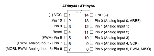
To blink the LED, we need to first understand which LED goes to which pin. Here is the pin map.

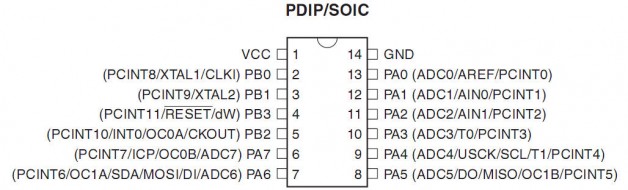
I looked up my board and here is what I have, yours might be different. It’s handy to put this in your code when coding and debuting your hardware, so you don’t need to look it up over and over again.
LED 1 = PA2 = Pin2
LED2 = PA3 = Pin3
LED 3= PA7 = Pin 7
Button = PB2 = Pin 8 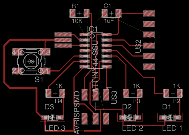
Below is what I use to replace the hello.ftdi.44.echo.c file. To avoid confusion, I rename the hello.ftdi.44.echo.c files. to blink_and_button.c. I then open the hello.ftdi.44.echo.c.make file and edit the first line from hello.ftdi.44.echo to blink_and_button.c. This will make the make file reference the blink_and_button.c when compiling the program. The .make file contains instructions on how to compiling the .c file.
There seemed to be a lot of questions about what PINA and DDRA and PORTB and such actually did.
#include <avr/io.h> #include <avr/delay.h> #define blink_delay 10 /* Pin Mapping LED 1 = PA2 = Pin 2 LED2 = PA3 = Pin 3 LED 3= PA7 = Pin 7 Button = PB2 = Pin 8 */ int main(void) { DDRA |= _BV(PA2); // Enable output on LED pin 2 DDRA |= _BV(PA3); // Enable output on LED pin 3 DDRA |= _BV(PA7); // Enable output on LED pin 7 // Loop while (1) { // Upward direction PORTA |= _BV(PA2); // turn LED on _delay_ms(blink_delay); PORTA = 0; // turn LED off _delay_ms(blink_delay); PORTA |= _BV(PA3); // turn LED on _delay_ms(blink_delay); PORTA = 0; // turn LED off _delay_ms(blink_delay); PORTA |= _BV(PA7); // turn LED on _delay_ms(blink_delay); PORTA = 0; // turn LED off _delay_ms(blink_delay); // Downward direction PORTA |= _BV(PA7); // turn LED on _delay_ms(blink_delay); PORTA = 0; // turn LED off _delay_ms(blink_delay); PORTA |= _BV(PA3); // turn LED on _delay_ms(blink_delay); PORTA = 0; // turn LED off _delay_ms(blink_delay); PORTA |= _BV(PA2); // turn LED on _delay_ms(blink_delay); PORTA = 0; // turn LED off _delay_ms(blink_delay); } } |
Now with the button
After I have all LED setup and blinking, I then added the button to trigger the if or else statement.
I created the bi-directional blink LED pattern, where the LED blink from left to right without button press, then the other direction when the button is pressed.
Here is my c code.
Here is my .make file which references the .c file at the beginning of the code.
To compile the program use this in your terminal (make sure you cd the right directory )
$ sudo make -f hello.ftdi.44.echo.c.make
To make the the chip using the external clock so the programmer can talk to it use.
$ sudo make -f hello.ftdi.44.echo.c.make program-usbtiny-fuses
To upload the program use this in your terminal
$ sudo make -f hello.ftdi.44.echo.c.make program-usbtiny
Now with the button
#include <avr/io.h> #include <avr/delay.h> #define blink_delay 10 /* Pin Mapping LED 1 = PA2 = Pin 2 LED2 = PA3 = Pin 3 LED 3= PA7 = Pin 7 Button = PB2 = Pin 8 */ int main(void) { DDRA |= _BV(PA2); // Enable output on LED pin 2 DDRA |= _BV(PA3); // Enable output on LED pin 3 DDRA |= _BV(PA7); // Enable output on LED pin 7 PORTB = _BV(PB2); // Activate button // Loop while (1) { if (PINB & _BV(PB2)) { // Upward direction PORTA |= _BV(PA2); // turn LED on _delay_ms(blink_delay); PORTA = 0; // turn LED off _delay_ms(blink_delay); PORTA |= _BV(PA3); // turn LED on _delay_ms(blink_delay); PORTA = 0; // turn LED off _delay_ms(blink_delay); PORTA |= _BV(PA7); // turn LED on _delay_ms(blink_delay); PORTA = 0; // turn LED off _delay_ms(blink_delay); } else { // Downward direction PORTA |= _BV(PA7); // turn LED on _delay_ms(blink_delay); PORTA = 0; // turn LED off _delay_ms(blink_delay); PORTA |= _BV(PA3); // turn LED on _delay_ms(blink_delay); PORTA = 0; // turn LED off _delay_ms(blink_delay); PORTA |= _BV(PA2); // turn LED on _delay_ms(blink_delay); PORTA = 0; // turn LED off _delay_ms(blink_delay); } } } |
Programing with Arduino
Use it like Arduino, here is the pin map.
Here is my blinking code & video
Using internal pullup to sense the push of the button since I don’t have a pull up resistor on the board.
pinMode(buttonPin, INPUT_PULLUP);
1 2 3 4 5 6 7 8 9 10 11 12 13 14 15 16 17 18 19 20 21 22 23 24 25 26 27 28 29 30 31 32 33 34 35 36 37 38 39 40 41 42 43 | const int buttonPin = 8; // the number of the pushbutton pin int buttonState = 0; // variable for reading the pushbutton status int switcher=0; int delaytime =80; void setup() { pinMode(buttonPin, INPUT_PULLUP); // using pullup to sense the push of the button pinMode(7, OUTPUT); pinMode(3, OUTPUT); pinMode(2, OUTPUT); } void loop() { buttonState = digitalRead(buttonPin); if (buttonState == HIGH) { switcher = 1; } else { switcher = 0; } if (switcher == 1 ) { digitalWrite(7, HIGH); delay (delaytime); digitalWrite(7, LOW); digitalWrite(3, HIGH); delay (delaytime); digitalWrite(3, LOW); digitalWrite(2, HIGH); delay (delaytime); digitalWrite(2, LOW); } else if (switcher == 0 ) { digitalWrite(2, HIGH); delay (delaytime); digitalWrite(2, LOW); digitalWrite(3, HIGH); delay (delaytime); digitalWrite(3, LOW); digitalWrite(7, HIGH); delay (delaytime); digitalWrite(7, LOW); } } |
Arduino Servo Library will not work with Attiny 44
ATtiny44 has 8-bit Timer/Counter, but the Servo-library relies on having a 16-bit timer available.
You can download Servo8Bit Servo library for the ATtiny45/85.
Adding a light sensor to light up the LED
int sensorPin = 7; // select the input pin for the potentiometer int led = 6; // select the input pin for the potentiometer int sensorValue; int brightness; void setup() { // declare the ledPin as an OUTPUT: pinMode(led, OUTPUT); } void loop() { sensorValue = analogRead(sensorPin); brightness=map(sensorValue, 0, 20, 0, 255); analogWrite(led, brightness); } |
Serial Print … Fail
Serial.begin(57600); // does not work
Attiny 44 does not have serial communication.