My original concept for the final project had to be scaled back considerably. I decided to eliminate the mechanical complexities of developing a bicycle hub dynamo and focus on the stereo amplifier and it's control systems, as well as the physical form of the speaker enclosures and their mounts on the bicycle.
Enclosures
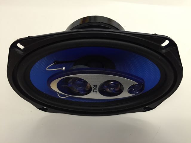
The speakers themselves are a pair of 6"x9" car speakers fom ebay.
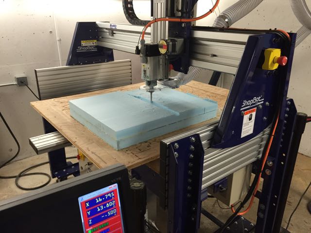
Milling
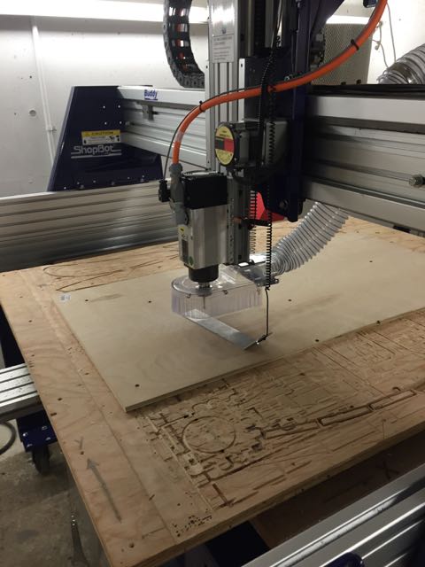
I designed enclosures in Rhino to be milled out of 1/2" plywood with a composite face and speaker mount. Here I am zeroing the Z-axis before I milll my plywood parts.
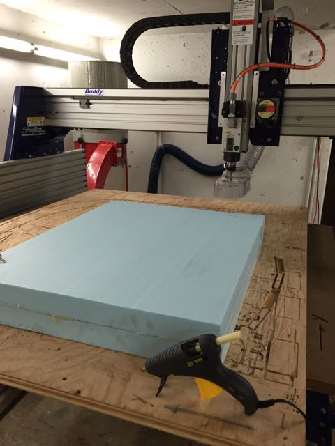
I used hot glue to fix the foam to the table. I ended up having to scrape hot glue off the table, so I recommed using scrap material that you can screw down to actually glue to.
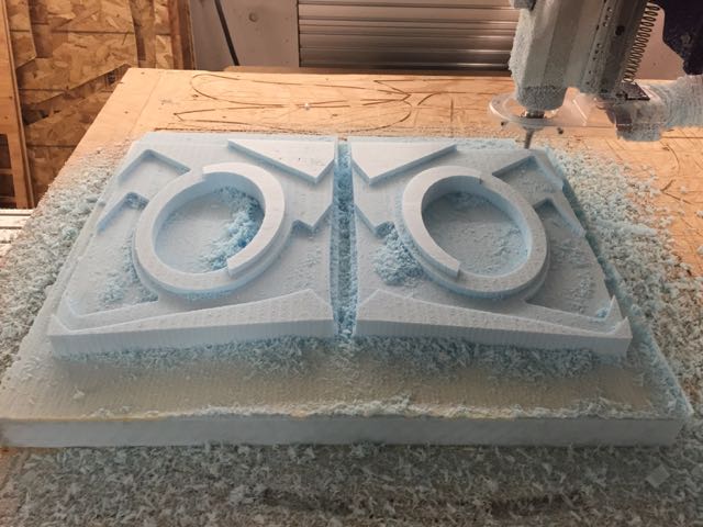
rough cuts
It looks like a crazy owl mask!
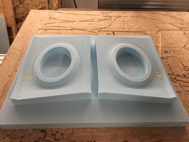
Here is the finished foam mold.
Composites
For the composite, I first laid drilled holes in the voids so that the vacuum wouldnt suck the material down into them. I then laid burlap and plastic wrap over the molds. I checked and it didn's seem like I needed any darts in the burlap, so I began mixing and laying down layers. I don't have any photos of this process because the resin is a mess and I couldn't pick up my camera.
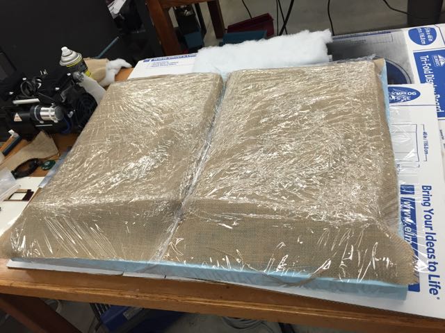
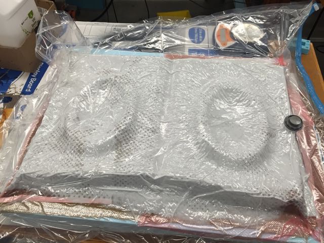
Because the mold is quite large - 24"x30", and it had to be fairly thick to be as stiff as possible for the speaker mount, I had to mix several batches of resin. I ended up doing 6 layers of burlap. I used the pink perforated plastic atop the composite, and padded it with batting.
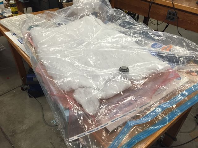
The vacuum and bag worked like a charm, and the burlap was flexible enough that it formed well to the complex curvature.
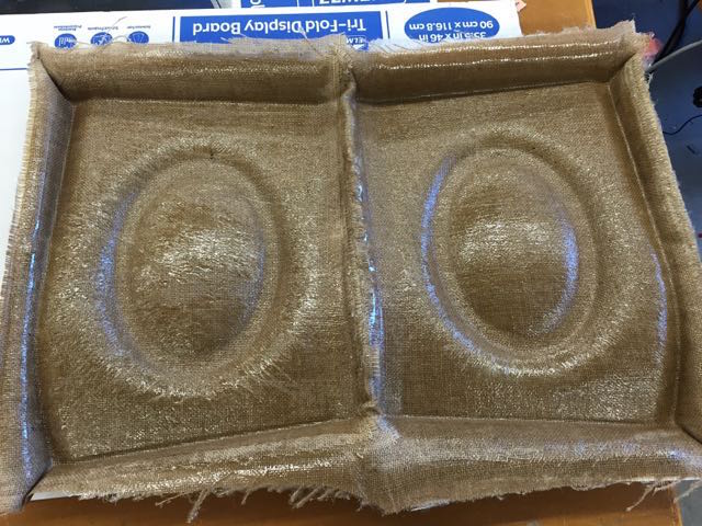
Tadaa!
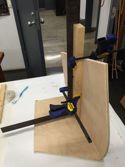
Assembling the speaker boxes, I used the ol' quick n dirty method known as Glue and Screw.
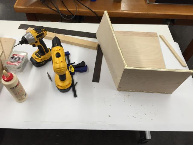
When all your usual shop buddies are busy with their own projects, clamps and jigs are your friends.
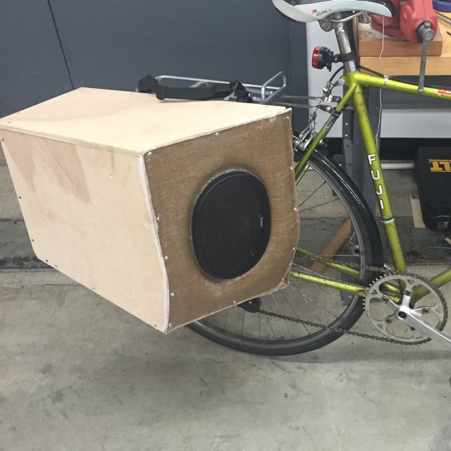
Finally, I used some old pannier bag hardware to attach the speakers to the bike rack.
Electronics
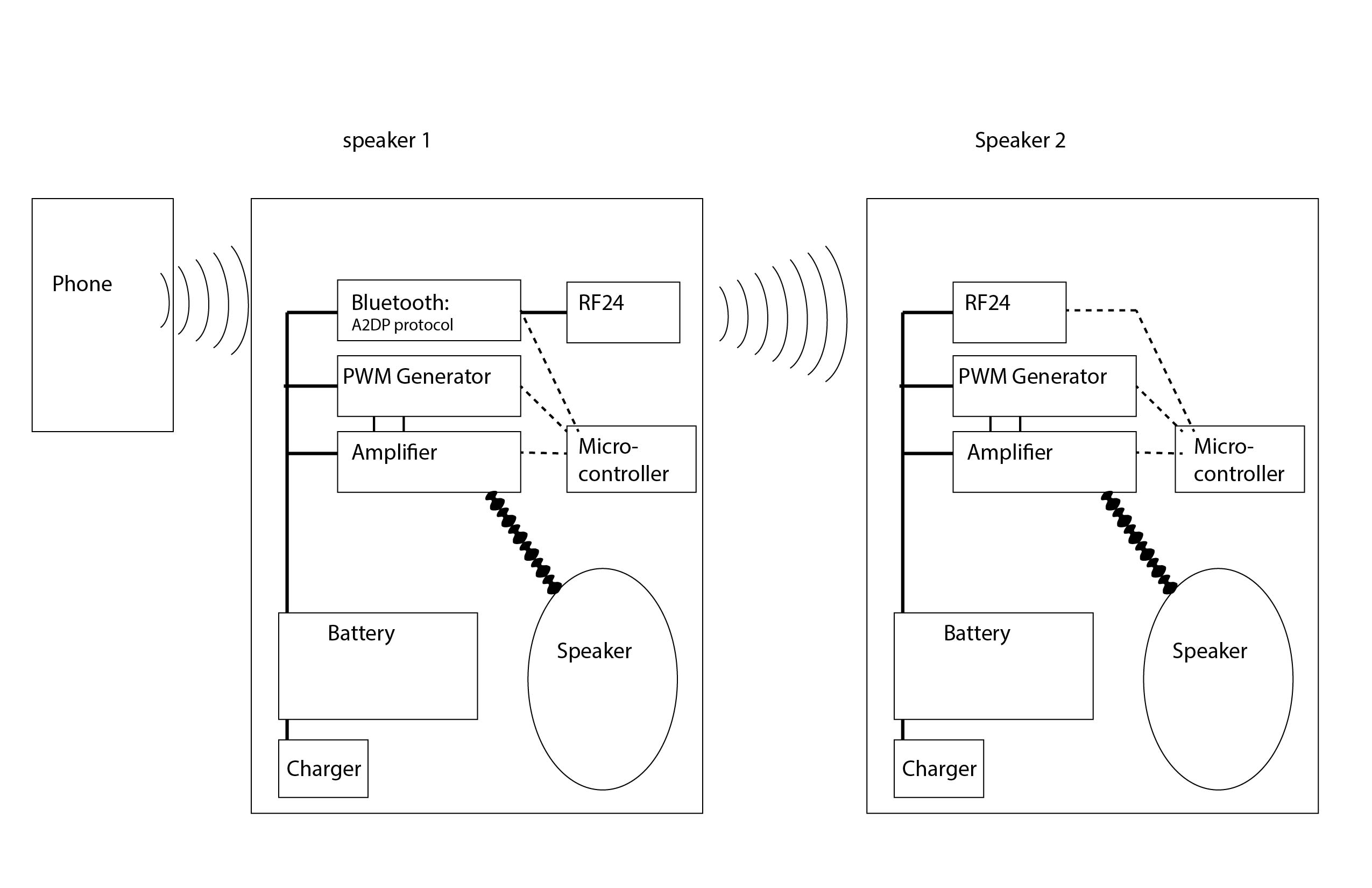
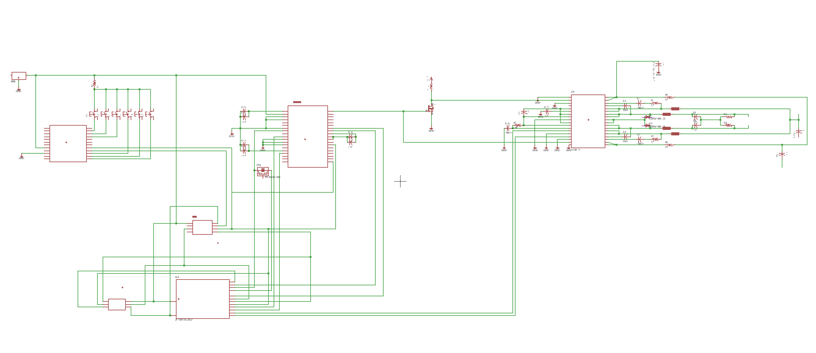
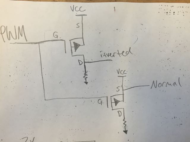
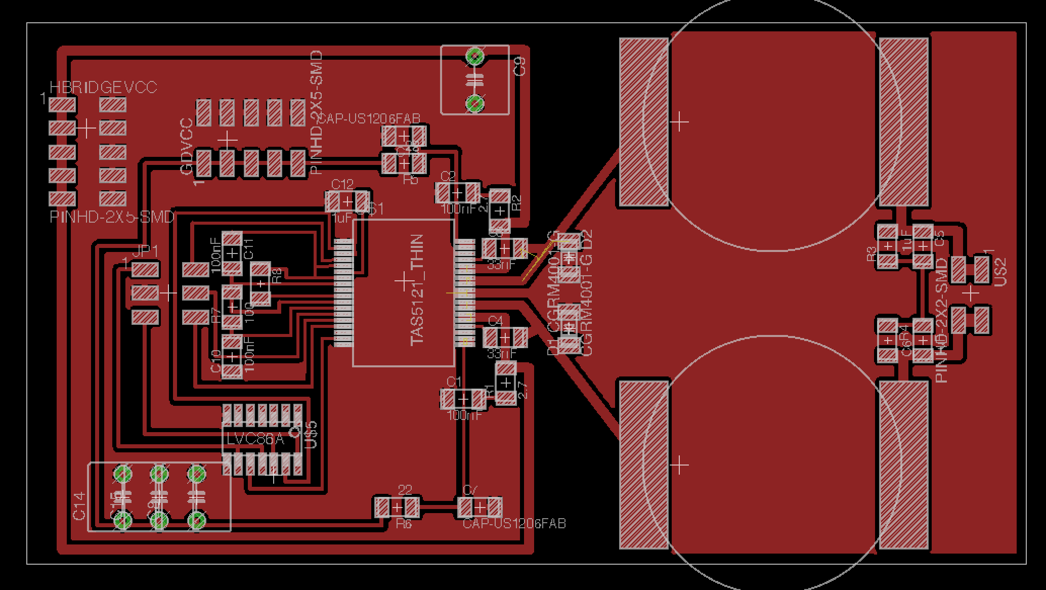
Here is a schematic showing the control systems and output stage of the system. This would be the "master" speaker and would include the bluetooth module that would recieve audio signals from a telephone or other bluetooth device.
PWM basics
I used a TI TAS5121 100 watt Class-D power amplifier. Class-D amps use H-Bridge circuits to convert a fast Pulse Width Modulation(PWM) signal to an audio waveform. Because they are switching amps and dont use FET's, they are very efficient. the downside is they need filters on the output to smooth out the signal into a cleaner oudio signal. Here is a diagram of one way that analog audio signals can be converted to a digital PWM signal. It is not the same method I intended to use, I just found it fascinating.
The PWM processor I bought was a TI TAS5086, which takes a digital audio input. I wanted to keep everything digital. Otherwise, I would have to convert a digital signal from the source to analog waveform and then back to digital and then BACK to Analog for the final output stage.
I added a NOTGATE to invert the PWM signal, because my PWM generator only had one output, and the amp needed two input signals per channel. Thanks to Jeff Duval for the help with the schematics. Two inputs drive the speaker in opposite directions. If it were not for this feature, the speaker would rely on its cone's elasticity or springs to return, and would be much less accurate.
Bluetooth
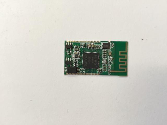
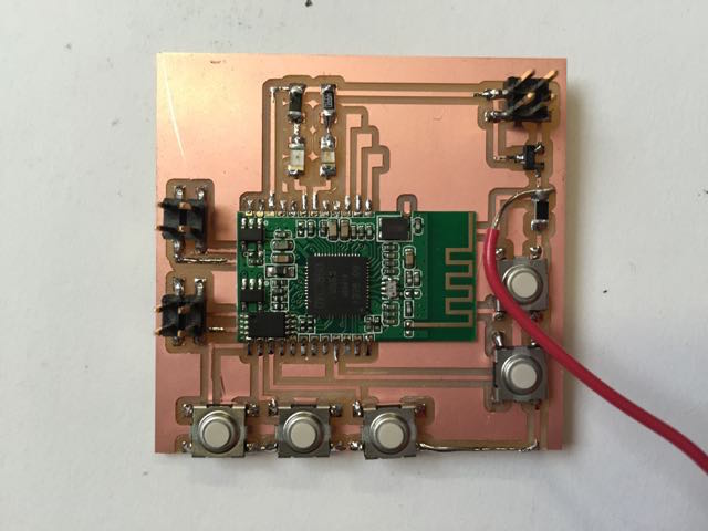
Here is the board I designed and fabricated for it. Notice the two headers on the left that I pulled out for Serial communication. The documentation is minimal. I had based my designs and parts based on being able to keep my signal digital all the way to final output stage. The bluetooth module is made with analog out, and I could not figure out how to access the serial output, and equally importantly the bitclock and Left/Right clock needed for signal timing, so I had to scratch my plans to use the PWM generator.
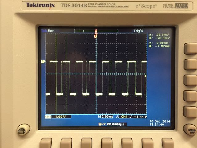
I began using my fabduino from earlier to simulate audio signals. Here is one such signal. It doesn't look nearly as clean as a motor drover PWM or an LED fader, because the pulse width itself has to change at the frequency of the audio signal, around 20Hz to 20kHz, so the signal looks very erratic.
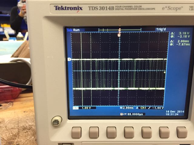
here was one moment in the signal where things seemed to clean up. this must have been a low frequency sound.
Amplifier
On to the main amp.
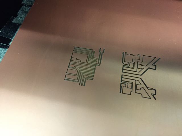
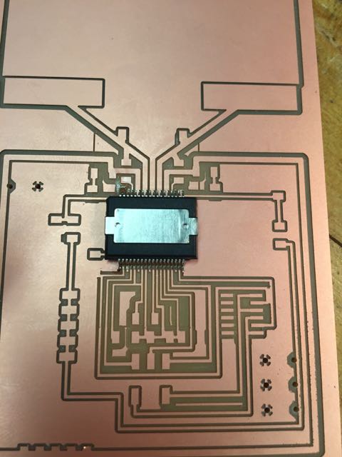
Milling the pcb was rather tricky. I had very small pins on the amp, and had to break out the 10 mil mill to mill the finer traces. I used illustrator to mask out sections so that I wouldn't need the tiny endmill for the entire board. This is all I had to do with the smallest endmill.
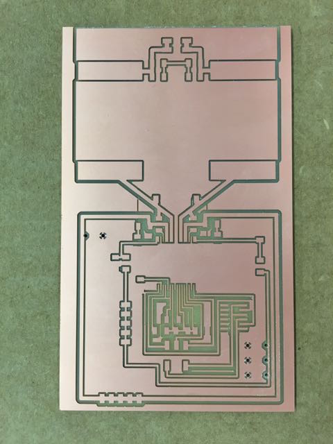
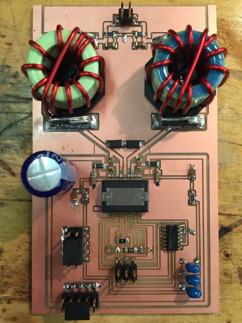
Here is the finished milled board, which I finished with 1/64" and 1/32" endmills. I did a few throughholes for the larger capacitors, also done in Illustrator. Purdy....
Soldering was a real pain in the neck. I did the ol glom and wick, but to get the solder off I had to hold the iron on the pins for a long time. Spoiler alert... I think this may have burnt out the amp chip.
The finished board!
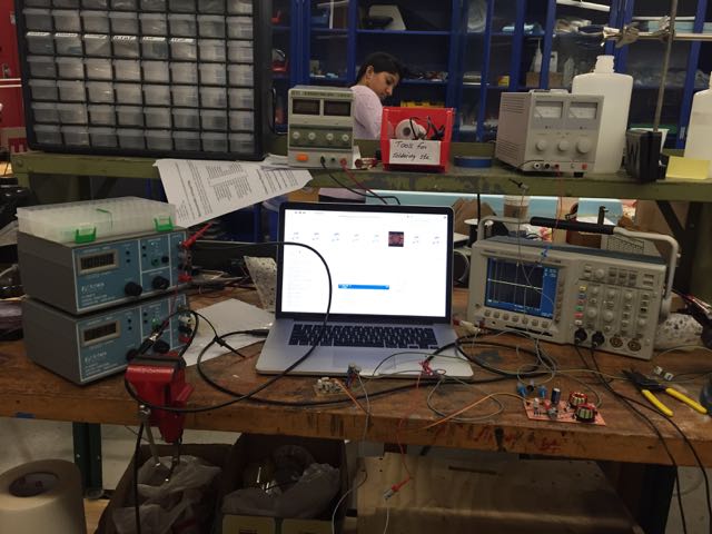
Then I attached the power and ....... voltage would not rise, but current sure did. Also, the chop got hot. I assume this means there is a short somewhere in the board.

Sooo, basically this was a fail, but I learned a ton. I bought a few extra chips so I hope to try again to finally get the Bike Boomer off the ground and on the road.