Input Devices
I wanted to look at a 2 axis accelerometer to further the project that I was considering in Casting Week. Looking at the board proposed by the class website, I realized it already includes an IC. I decided to instead link the accelerometer component directly to the Fabduino I had made in Programming Week. First I attempted to use the .c files that Neil provides to read the accelerometer output, but I was unable to figure out how to set the pins on the fabduino. I decided at this point to start using the Arduino IDE, so I had to figure out how to recognize the fabduino in Arduino and then load a bootloader.
Initially, in Arduino, there is no board equivalent of the 328p with a 20Mhz crystal. In order to find the board, we need to create a .hex file for the board bootloader. I followed this tutorial by Amir Lazarovich of HTM13, which helped at the start, but due to updated versions of gcc/avrdude, it didn't get me all the way.
I'll just go through the steps I used, with a special thanks to Amir.
This was done on a mac and assumes you have Arduino, avrdude and crosspack installed, and you used Neil's Fabduino with the atmega328p with a 20MHz crystal resonator. To make things easy, here are the modified
ATmegaBOOT_168.c file and the
ATmegaBOOT_168_atmega328_pro_20MHz.hex file for the board.
If you want just put them in this folder, ~/Applications/Arduino.app/Contents/Resources/Java/hardware/arduino/bootloaders/atmega/ and skip to step 3
or the long way
1. Go to ~/Applications/Arduino.app/Contents/Resources/Java/hardware/arduino/bootloaders/atmega/ and open the makefile. Find the segment for the atmega328_pro8. Duplicate the whole segment including the isp section, <atmega328_pro8> to <atmega328_pro8_isp: isp> within the makefile, and then change it to match your board's clock. Rename it, I called mine atmega328_pro20, change the AVR_FREQ to "20000000L" for 20MHz. Then save it and close the makefile.
2. Now you must make two small adjustments to the ATmegaBOOT_168.c file. Whe you attempt to run the make command, there are some obsolete commands that are not included in current libraries. I consulted the oracle(google) and found the problematic lines. Now my .hex code compiled and made a file called ATmegaBOOT_168_atmega328_pro_20MHz.hex. This showed up in Arduino as a new board, but for some reason it still wouldn't burn a bootloader. After a little more sleuthing, I found that the file was too big and so I went back to the makefile and changed a line that controlls how the hex code is optimized. These steps can be found here. Do a <make atmega328_pro20>, or whatever you called your board in the makefile. This hex should now work.
3. Go to Arduino IDE. Go to your menu tools>board and select your board(ATmega328P, 5V, 20MHz External Ceramic Resonator). Go to tools>Serial Port and select USB port. Go to tools>Programmer and select your programmer(USBtinyISP for me). Then go to tools>Burn Bootloader.
You should now have a working Arduino!
Now for the fun part!
Fab the Accelerometer-
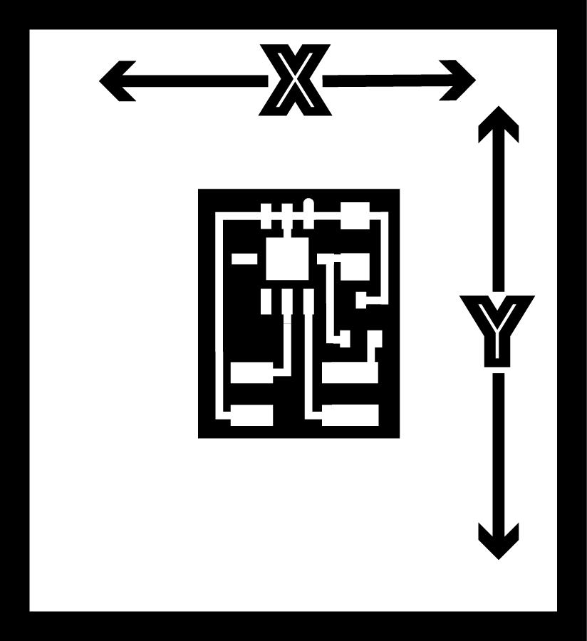
I used Neil's accelerometer board as a starting point, but didn't need the tiny45 IC to control it. My board just has a 2x2 header, a 3.3v voltage regulator, a 1uf capacitor for noise, and the 2axis accelerometer provided in the fab inventory.
here are the traces, which I made in Illustrator.

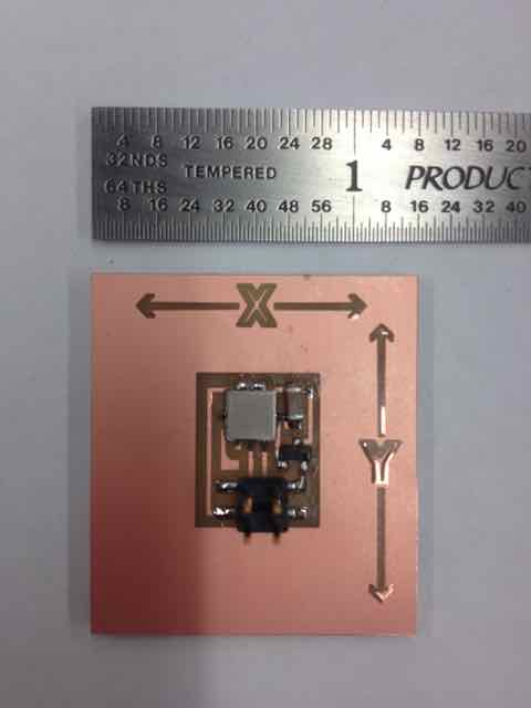
Milling went fine, but I had to clean up a bit afterwards.
I stuffed the board,
and plugged it in!
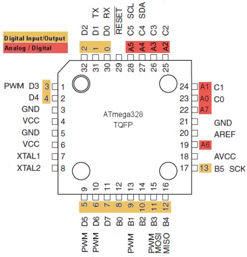
This image came in very handy, it shows the pins on the 32 pin 328p, and thier names in Arduino.
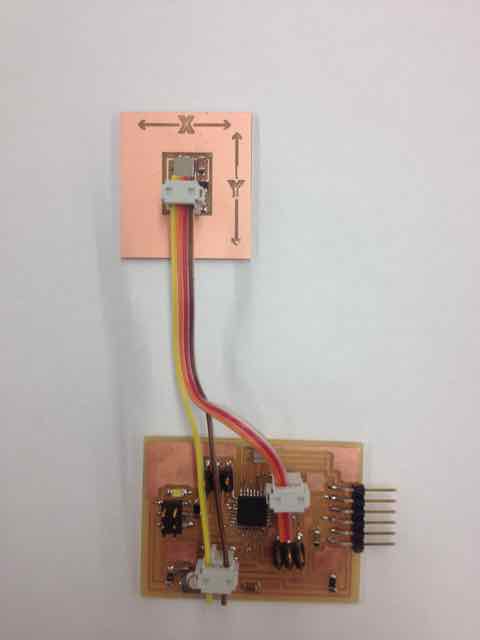
initially I used the ADC header on the Fabduino, because it has VCC and GND pins. It didn't seem to work so I tried a digital input, which involved splicing power from the ADC header and digital I/O from pins 3 and 4.
It STILL doesn't work, so I went to the Oscilliscope.
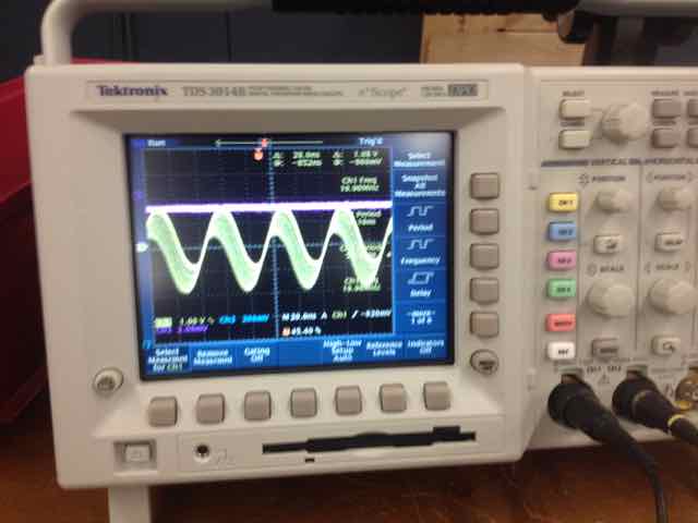
I realized there was a gap somewhere because the accelerometer wasn't getting any juice. I poked around and found a tiny scratch on one of the vias. I soldered over the gap, and then everything worked fine. Here is the output from the accelerometer!

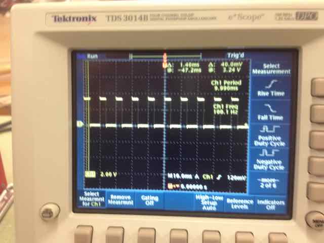
If you look closely you can see the duty cycle changes between the two images. The accelerometer varies the "up" time in relation to the frequency to send the signal. Finally, I used this Arduino code to read the signal. I had to change the input pins, and then I could read the accelerometer input in milli-g's. I used a little trigonometry to convert the milli-g's into an approximate angle.