Kim Smith
Make Something Big
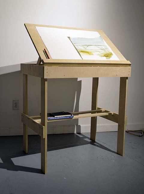
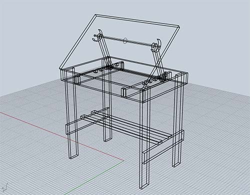
This week was super fun. I really enjoyed making this. I am feeling more comfortable with 3D CAD tools and I am now fairly confident on the ShopBot. Make something big...I decided to make a drafting table for my studio. I wanted one that was standing height because I like to stand when I draw/work and don't really have a good set up. I looked at some plans and images for a bit, trying to conceptualize what I was making and how it would fit together. I could see it in my head and was pleased that my Rhino skills are improving and I could start to map it out. Still wishing I had SolidWorks because I was trying to design some mechanical function for the desk and just felt like Rhino was more of a sketch than a precise model.
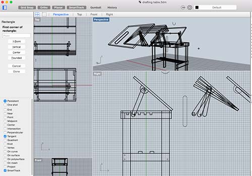
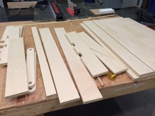
I realized that the most difficult part of the design would be in the angle of the desk, and creating a mechanical movement that allowed for the top piece to move and stay and prop up at multiple angles. Again, I used Rhino for this and the rotate command to sketch it out. Matt's recitation in mechanical design was helpful, and in the end I realized I needed to use a program like Solid Works and still felt like I was kinda eyeing it. I created multiple designs for all potential rotations and created my design based on one-inch increments. I decided to purchase some higher quality birch, and opted for 3/4 inch thick plywood. The material was beautiful, but heavy. And required slight tweaking to my design, but not much, as the individual pieces would become 2D shapes for cutting. Little in my design was truly dependent on the thickness of the material; I decided not to use a press-fit construction, mostly because I found it mentally cumbersome and not applicable to the design I wanted.
ShopBot
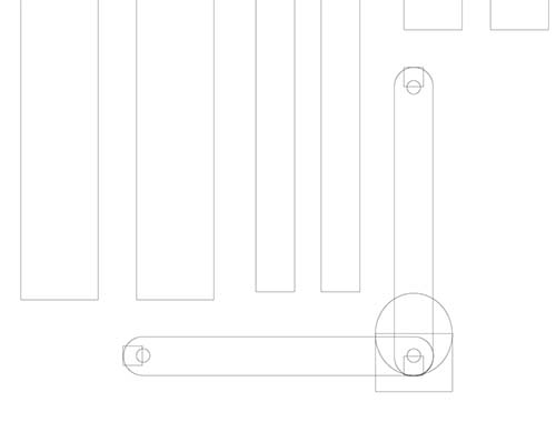
Shop training was a bit intense; a lot to learn and many variables. I took tons of notes, but when I went to use the machine, we fumbled around for like 4 hours. It was frustrating but satisfying when we figured something out. I had help from a few people, but it was still confusing. We had trouble getting the shopbot to even communicate with the computer. First step was to load the image into PartWorks. This program was super annoying. I had built my original design in Rhino and then plotted it out in Illustrator so that I could lay out the 2D vecotrs on a 4 x 8 ft page.
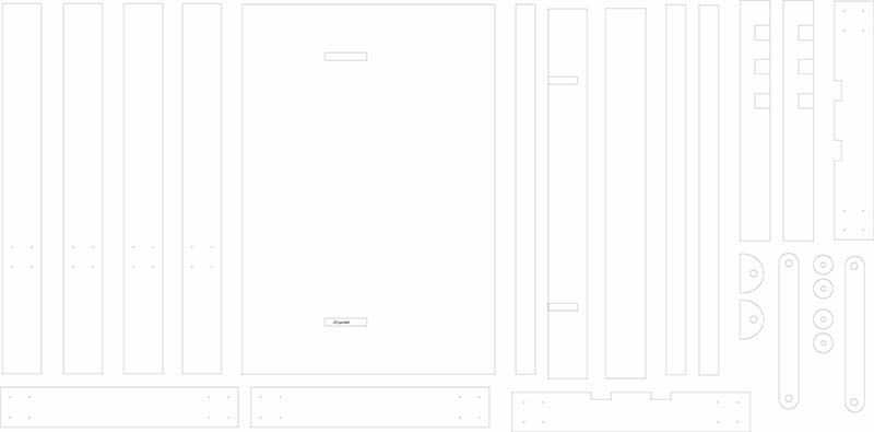
When imported into PartWorks, I had to re-orient it to the page. My pieces were a tight fit, but in my plan it looked as though I had enough margin. I barely did. After importing, we created tool paths. I set up 3 different toolpaths, and exported them individually. Soon learned that a few of my vectors were not quite right, and I really wish I would have just corrected them in Illustrator instead of trying to make it work in PartWorks.
Toolpaths:
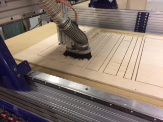
- 1 Profile: .25 endmill in cuts, simple holes in the pieces that operate like washers. I made this a separate toolpath to ensure that these cuts were made first so that the pieces did not move around during the larger cutting.
- 2 Pocket: .25 endmill with .25in pockets. These pockets are places where other pieces join together. I created them in joints where there would be force placed upon it, so that the pocket would hold the piece in place
- 3 Profile: .25 endmill; these would be my main profile cuts that would cut out the pieces.
I had originally placed holes for screws to cut, but scrapped it while we were cutting because of time. Instead, I manually drilled them with the bit after the sanding. For the profile cuts, I set the cut depth for .8, since my material thickness was .75 inches. This would be 3 passes with the .25 endmill in order to cut through.
Steps for the ShopBot, very briefly
- 1 Import dxf into PathWorks
- 2 Ensure closed vectors in image; reconfigure to optimize the space on the material
- 3 Create toolpaths. Select small features such as holes or pockets first so that they stay in place during cutting. Set toolpaths with corresponding endmills appropriate to the size and depth of the cut. Cut depth should not be greater than the diameter of the endmill. So set up multiple passes to ensure cut through. Set up sizes and cut depth/passes for individual toolpaths.
- 4 Export each individual toolpath as a Shopbot file.
- 5 Open up the ShopBot applicaiton on the computer and turn on the main red ON switch on the ShopBot.
- 6 Use the control pad to move the machine out of the way in order to place material on surface
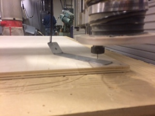
- 7 Secure material to surface; first create clearance holes in the material and then screw into the material and into the top of the sacrificial layer. Place at least 6 screws so that the material is secure and flush to the surface.
- 8 Use control pad to job the head toward 0,0. Use the blue Reset button to reset the connection between the machine and the computer so that the two are communicating.
- 9 Use the correct collet to place the endmill into the machine. Give it enough space to mill into the material but not too much so that it doesn't wobble during cutting.
- 10 Zero X and Y by eyeing the mid point of the endmill to the edge of the material that is x and y
- 11 Use the automatic Z zero that uses the metal plate to measure the connection with the surface for the correct z axis.
- 12 Upload first toolpath
- 13 Turn on spindle with key
- 14 Start the cutting. Keep hand near emergency stop
Bad News
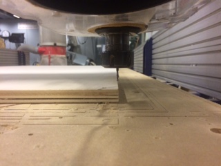
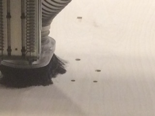
So after carefully following the instructions and having difficulting getting this far, we started the machine for the first toolpath. When I hit start, the maching jogged toward the first spot, but plunged into the surface as it moved across. This was terrifying! Within half a second my beautiful birch was scarred. I should have practiced on the OPB but there was just no time, the schedule was hardly available and everything took much longer than any of us anticipated. So, we started from the top of setting up the Z axis, concluding that that must have been the problem although I really have no idea why. Starting over, it worked, and worked beautifully. First toolpath was to create holes; and then the next was the pockets. I kept the endmill the same size so did not have to change it.
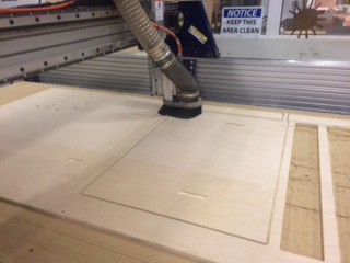
It seemed like the cuts were going really well; but the two pieces that had the faulty vectors gave me trouble and so the machine completely ignored them. I had to create new toolpaths, leaving the piece and the axis as is and start again with only a few more cuts. Also, as the machine was cutting, the y axis seemed a bit off from my plan, because it was very close to the edge. So close that we had to stop the machine and remove a screw. But we were able to stop the machine and then continue without losing place.
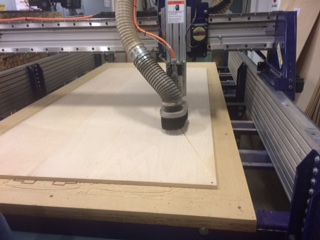
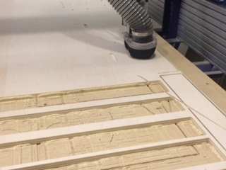
Unfortunately, when I went to remove the pieces, some were not completely cut through. I should have set up a deeper cut depth, and it was clear that the z axis sloped downward as it progressed on the x axis. ugh. Worst part was that there was no time to run it again, really behind schedule and so I figured I would do my best to pop them out.
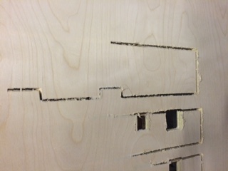
In some places where it didn't cut all the way, it was very, very thin; but, in others, it was more difficult to remove. I pretty much just used a chisel to pierce through the veneer very carefully. Super frustrating because I wasted a lot of time getting these pieces out when the whole point was the ease of the machine. I also then spent about an hour sanding; and the amazing thing was that they looked great. Hardly noticable, except a couple pieces and they were not so bad. Sanding removed the jagged edges.
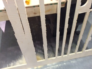
Assembly was quick and easy. I used nails after drilling all of the nail holes ahead of time. In a couple places, like my pockets, I used wood glue and clamps.
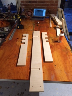
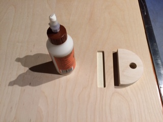
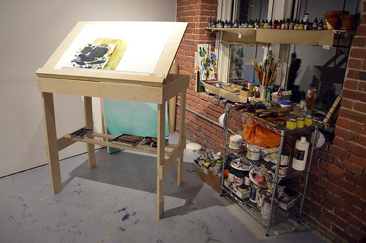
Hinges were used with the desk top so that it could swing up and down. For my moving parts, I secured my wooden washers with some muslin; it was a simple solve with what was on hand and I liked the way it looked. I sanded the blemishes after hammering, and tested out the different desk heights.
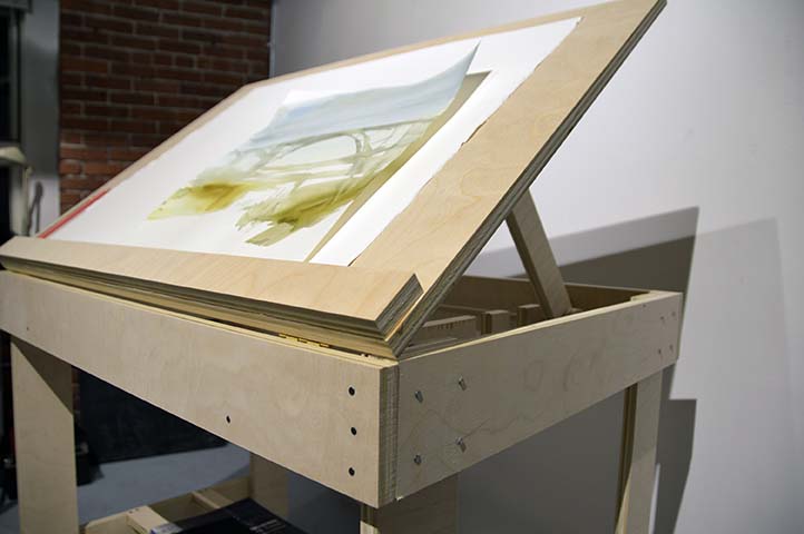
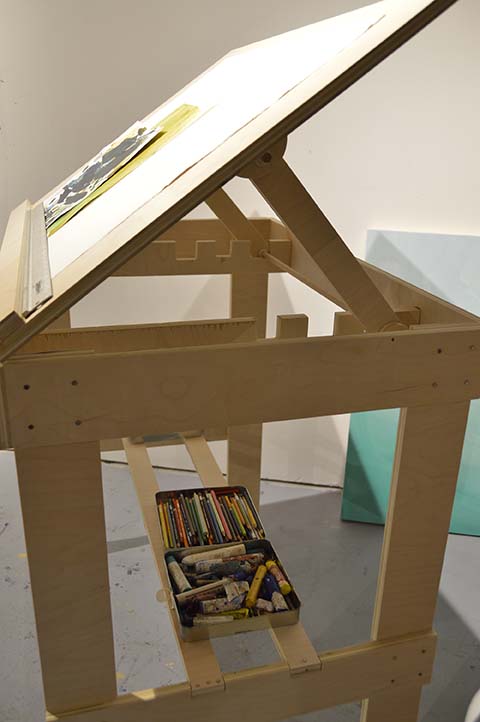
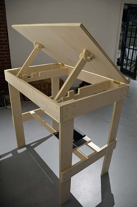
My New Desk!
Design Files
Drafting Table RhinoDrafting Table Illustrator
Drafting Table DXF