Kim Smith
Output Devices
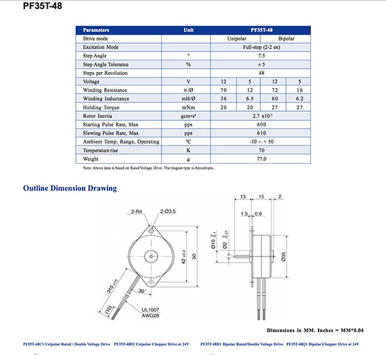
Assignment: add an output device to a microcontroller board you've designed and program it to do something. I started this assignment with a design for a speaker. After two tries, I could not get it to program. So I moved on to design a board for a unipolar stepper motor, that I would use for my final project.
Designing the Board
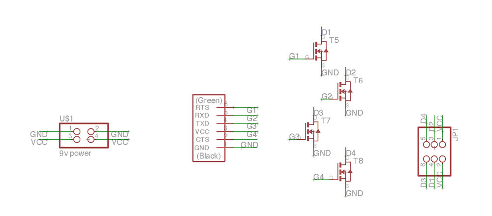
Finally understand how to connect things in Eagle...Created a simple board,using N mosfets to connect to the motor. The board will connect to the fabduino.
Milling the Board
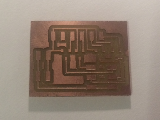
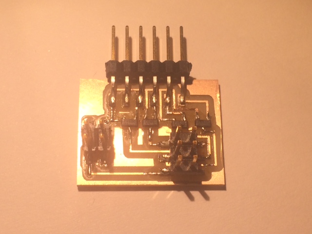
I used the Modela this time and the board came out beautifully. I milled 3, one of which the traces did not cut all the way through, not sure why, but I think the surface wasn't completely flat. In my settings, I have been tricking the machine by adjusting the endmill's tool size so that it reads smaller, in this case, .3 instead of .4. This way the the toolpath is generated for narrow clearances. I also have been washing the boards with soap and water and it removes all the excess dust and some of the burs.
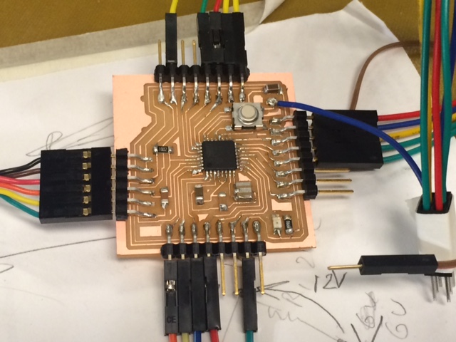
Stuffing the Boards
Soldering has become easier, and this board was relatively easy. I soldered two identical boards that will both each run a unipolar stepper motor. But are controlled by the Fabdruino running with an Atmega 328.
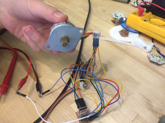
Programming the Boards
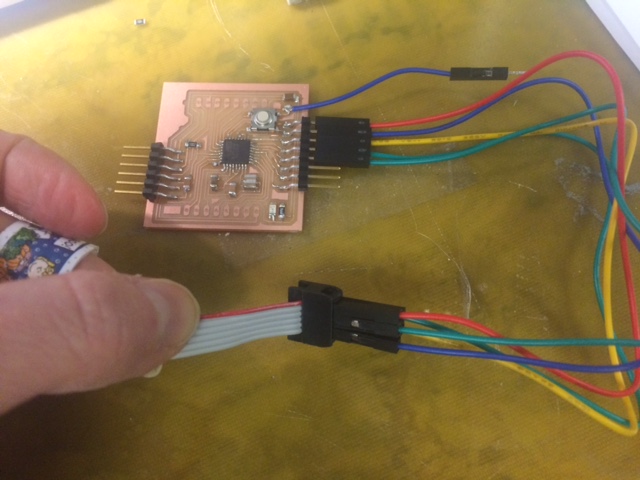
I am running two motors on the atmega 328, using an external resonator 8mHz. I programed/tested/troubleshot each one individually and later will compile one code to run them simultaneously. The most difficult part was probably connecting everything, as it was super easy to screw things up and I had too many wires and connections...I should have planned better for this, but also learned a lot about how to connect things together. I connected my first board to the Fabduino, after deciding upon the pins I would use. I used the datasheet to determine how I would configure everything for the two boards. I also connected the ground from the motor boards to the fabduino. In order to program the first board, I connected the fabduino to the usb port through the FTDI cable. This supplied power to the fabduino; and I will use an additional power source to run the motors, connected to the motor boards. In order to program everything, I labeled all of my pins/boards and did the following connections, taking notes of all the pin numbers so that I could edit the code to reflect my configuration.
- Fabduino Pins to AVRISP (MOSI, MISO, GND, RST, SCK, VCC)
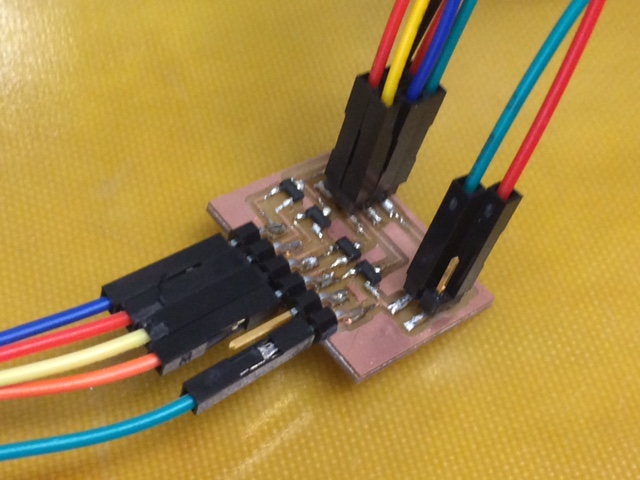
- Atmega Pins to Motor Board (corresponding with N mosfets --> Motor Pin Header
- Motor Pin Header --> Corresponding wires on the stepper motor
So basically you have to connect and make note of the pins from the Atmega that are ultimately connected to the specific wires on the stepper. Also! important to try and use a stepper with a known datasheet and reliable color wire configuration.
Connecting to the Fabduino, using two Ports to connect to 2 stepper motors
Pins in from the Atmega; and then pins connected to the corresponding wires on the stepper.
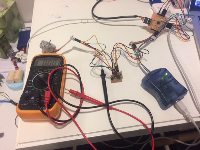
After ensuring the connections, I used the AVRISPmkii to program from the fabdruino. I used Neil's C code, the half program and edited it to set my pins for the motor wires and also to simplify the code so that the motor would make half steps ccw. I also modified the makefile so that I set the correct microcontroller, clock speed, and programmer. I first ran the makefile from the terminal, after navigating to the folder with the saved code files:
make -f hello.stepper.44.half.make
make -f hello.stepper.44.half.make program-avrispmkii
make -f hello.stepper.44.half.c
And it was successful. I then tested it with power, and it just vibrated. Amanda helped me set it up on the osciliscope in order to see where and how the current was flowing. We saw that the board was receiving power, the schematic looked good, and the soldered connections were solid. Turns out, I had the wires misconfigured--they were backwards in a female header. Triple check connections! After I rewired it, it worked perfectly.
Design Files
echo C MAKEDesign Files
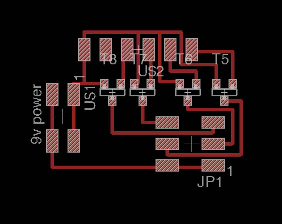
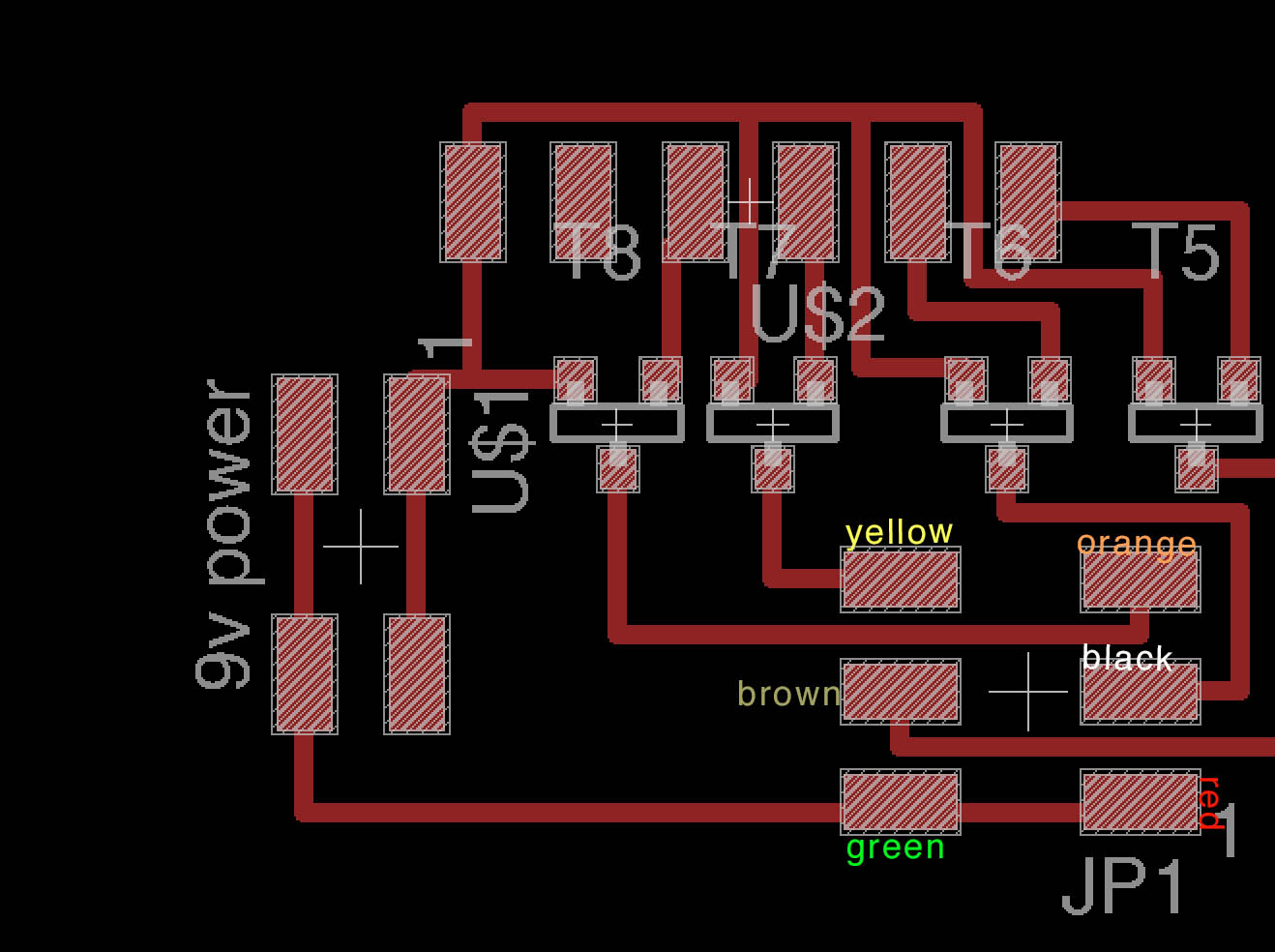
Unipolar Stepper Motor SchematicUnipolar Stepper Motor Board
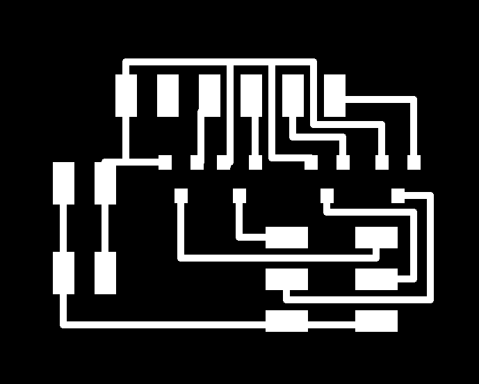
Unipolar Stepper Motor TRACES
Unipolar Stepper Motor TRACES
Fabdruino Reference