Kim Smith
Input Devices
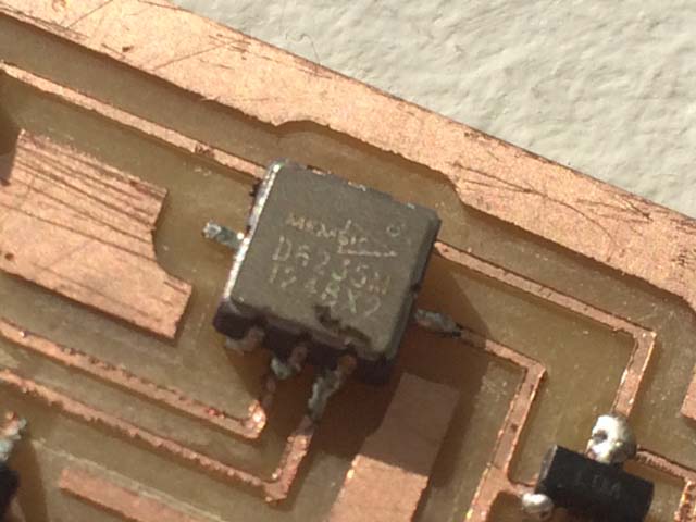
Assignment: Add a sensor to a microcontroller board that you have designed and read it. I have been trying to make a lot of boards, starting with a new one each week instead of using pre-existing boards. I am getting better and faster, but still working on it. I opted to create a 2D accelerometer this week. First I read up on some things and tried to get a better understanding of the process and components. The accelerometer I used is the MXD6235MP by memsic. I read the datasheet and learned about the pins.

Designing the Board
I used Eagle again. I am still learning electronics, so I referenced Neil's design for the board, and this helped me gain a better understanding of the board.
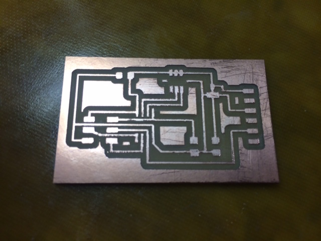
Milling + Stuffing the Board
Milling went really smoothly. I took the time to really clean the board after milling, cutting away some small areas, and removing all of the burs.
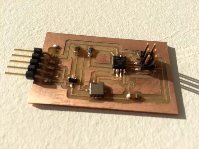
While I am getting better at soldering, the accelerometer presented some new challenges. Because the pad are on the underside of the board, some special skill was required
Soldering the Accelerometer
- Place small dots of solder on each of the pads on the underside of the component.
- Place small dots of solder on the copper surface pads of the PCB
- Use the copper braid to remove excess solder on the PCB, so that a nice thin layer of solder exists only on the board
- Hold the components above and close to the board with tweezers
- Use a heat gun with the spot attachment to direct heat on both of the surfaces as you slowly lower the piece down
- The solder should attract eachother and you can place the piece on the board, and from here can move it to position is correctly.
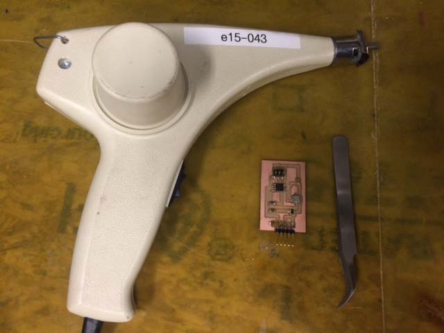
Programming the Board
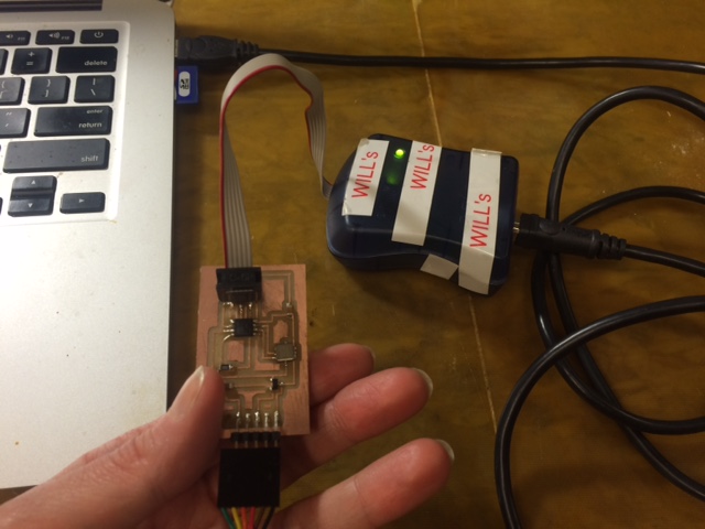
For this, I used the avrsmkii to program it. After checking for connections on the multimeter, I hooked the PCB to the computer with the programmer.
I downloaded Neil's code, the make and c file and the python script, and opened up terminal to navigate to the folder with the code. I then edited the make file so the it included a line for the avrispmkii programmer.
I then typed in the folloing commands:
make -f hello.MXD6235MP.c.make
make -f hello.MXD6235MP.make program-avrispmkii-fuses
make -f hello.MXD6235MP.make program-avrispmkii
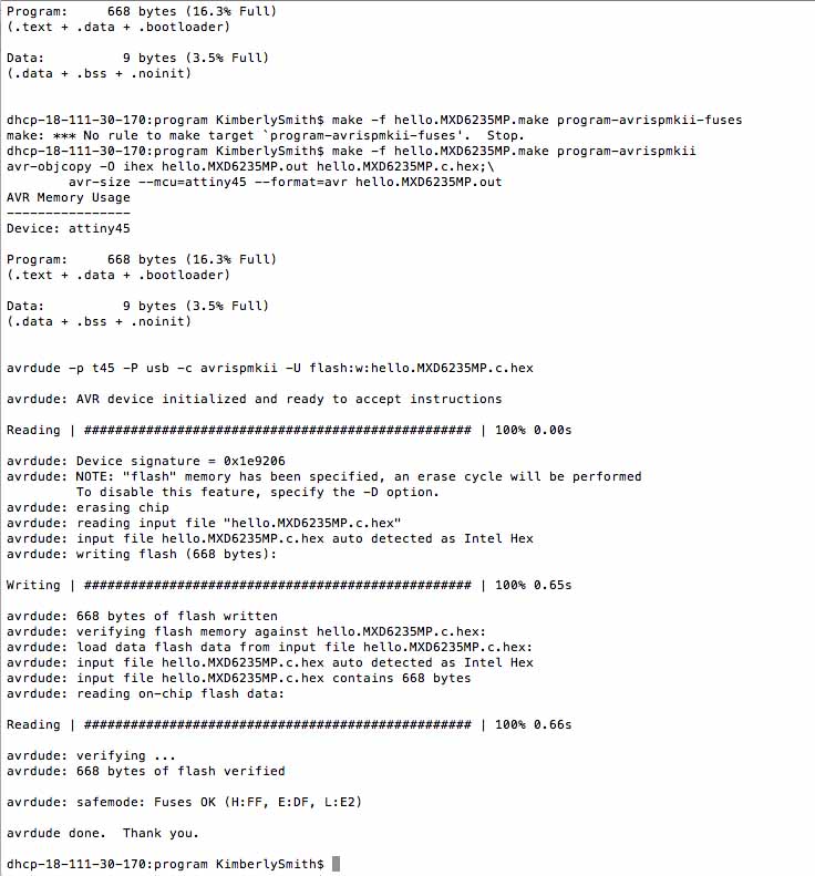
I was super excited to see that it programmed successfully. I then ran the Python script from Neil. In order to locate the serial port I typed in the following:
python hello.MXD6235MP.py /dev/tty.
In order to locate the correct port I then hit the tab key to find a series of options for autocomplete and then located the usb serial.
python hello.MXD6235MP.py /dev/tty.usbserial-FTH9JK8N
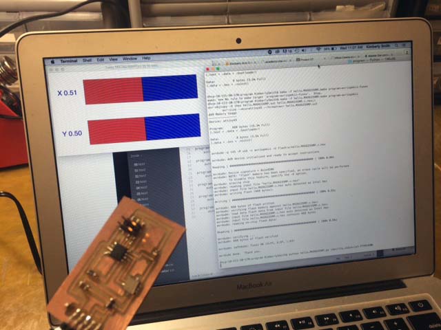
Then the window popped up with the accelerometer x and y markers. It was working! The coordinates did not fluctuate much, however, and in order to get much reading, I had to move it quite a bit.
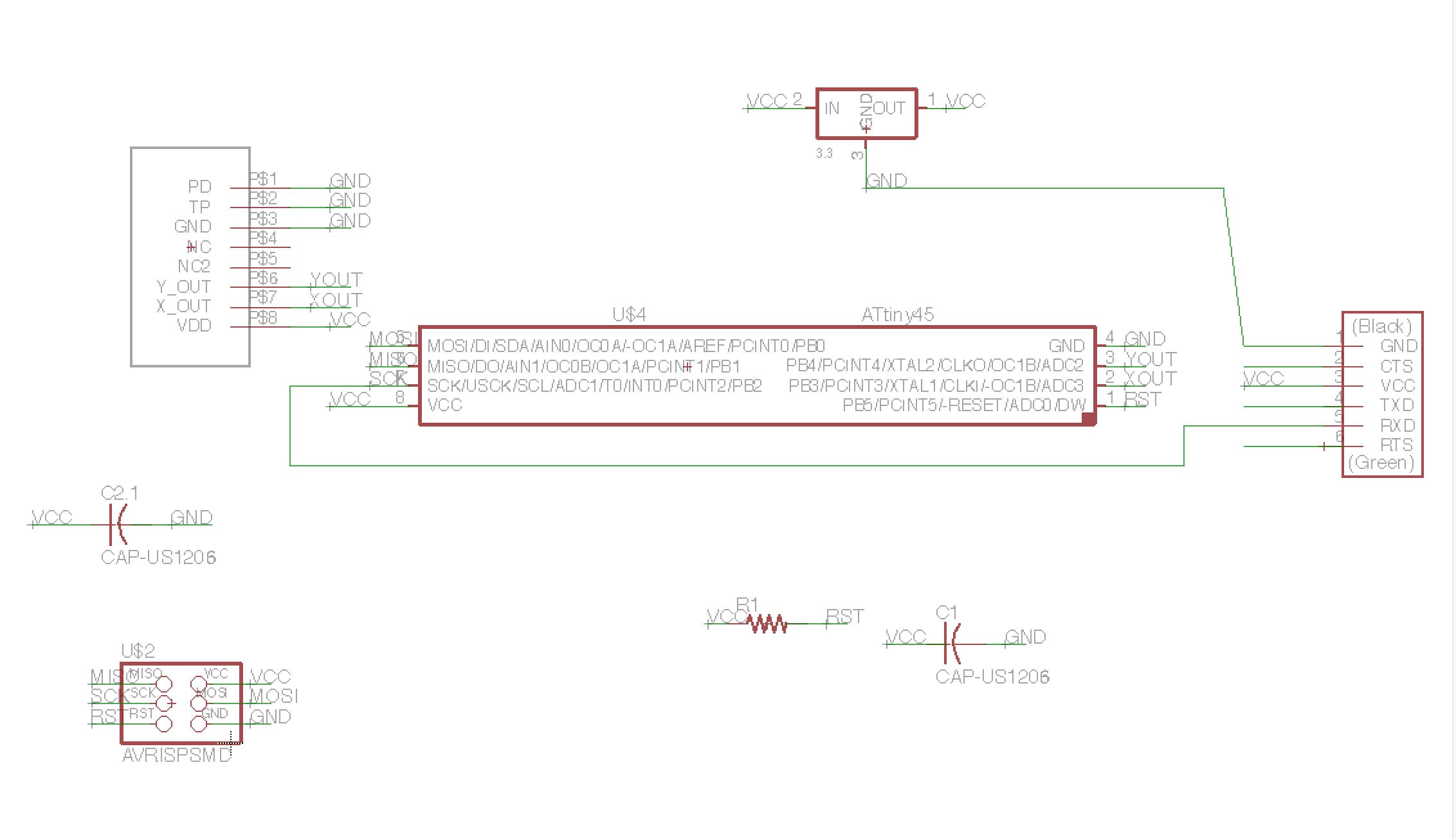
Design Files
2D Accelerometer Schematic2D Accelerometer Board