Kim Smith
Embedded Programming
Assignment
Read a microcontroller data sheet program your board to do something, with as many different programming languages and programming environments as possible.
First step was a lot of reading. I didn't know how to program this and I was even more confused after recitation. I figured that the big picture was to get the attiny to communicate and then program it through the ISP to do something. At this point I was less concerned with what it would do and just concerned with getting it to communicate. I started with this tutorial.
Process
From tutorials and the class page, I gathered and downloaded what I would need:
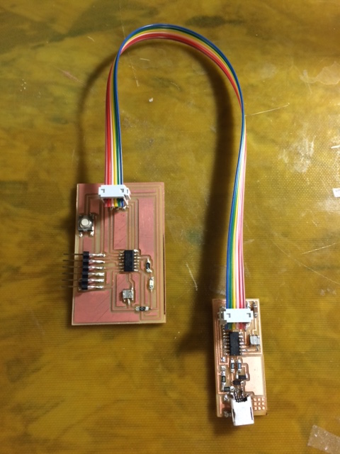
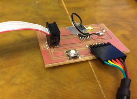
- Fab ISP
- ATTINY PCB
- Download Crosspack for AVR Development
- hello.ftdi.44.echo.c
- hello.ftdi.44.echo.c.make
- term.py
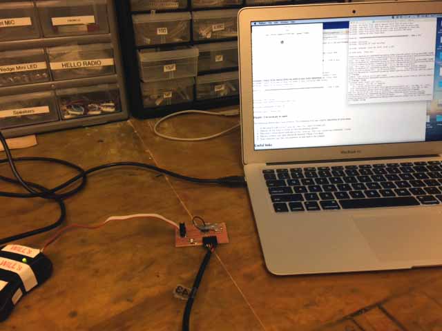
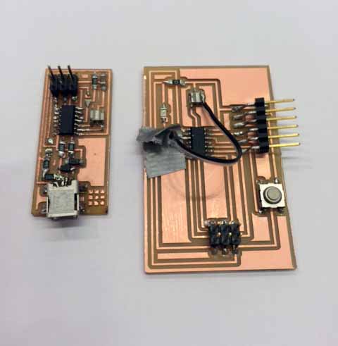
Then I hooked the ISP up with a miniusb in the USB port and connected the two boards. At the time, I did not have the correct orientation, that is, lining up the red wire with the correct pins on both the boards. In retrospect, I realize that that was probably my issue with the Fab ISP.
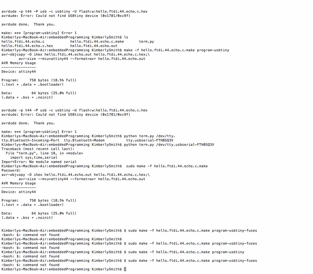
To start, I opened up the terminal, and entered the following commands:
- make -f hello.ftdi.44.echo.c.make
- make -f hello.ftdi.44.echo.c.make program-usbtiny
Then I received the first of many frustrating error messages, most of which said something about an inability to locate the usbtiny.
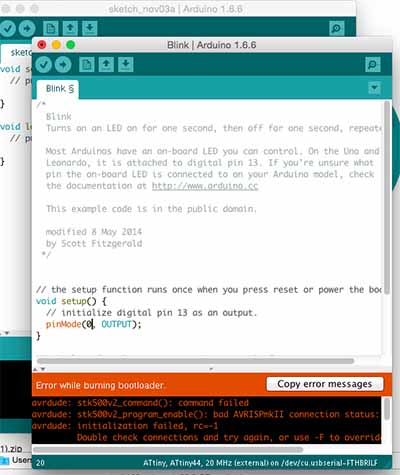
After trying to troubleshoot on my own by searching around previous years' pages and the internet, I did not solve the problem and then began to wonder if something was either wrong with the board or my computer recognizing the correct port. I really had no idea. So Caroline helped and we realized that everything that was supposed to be connected was connected. Frustrated, I decided to get help from Amanda. We kept getting similar error messages and at this point, I tried a completely different route, installing Artduino and using those libraries and commands. Still, I kept getting error messages, and was even unable to install the bootloader.
Error Message from Arduino: "avrdude: initialization failed, rc=-1 Double check connections and try again, or use -F to override this check."
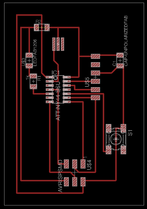
At this point, I returned to my schematic, and with Amanda's help, she realized that my resonator was not connected to the right pin. So...I had to hack a wire on there and resolder.
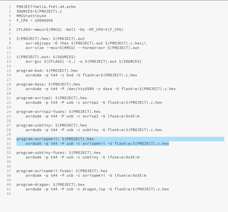
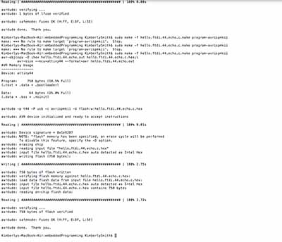
After resoldering some wire, everything looked pretty good and I decided to try again with the C code using the Fab ISP. But, I got the same error code that said "unable to locate directory usbtiny" This was incredibly frustrating!! But, I figured there could still be a problem with the Fab ISP and so I tried to use the programmer. In order to use this and the code I was working with, I had to alter the C code in order to specify the correct programmer.
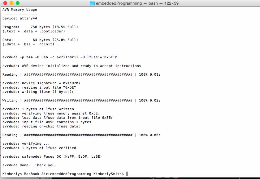
After this, I had some little issues with typing in the commands, but ultimately, it worked, and I had the board communicating and ready to be programmed.
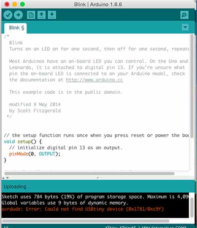
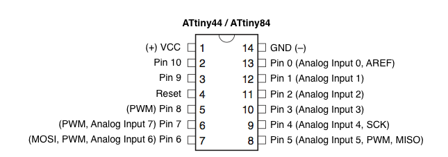
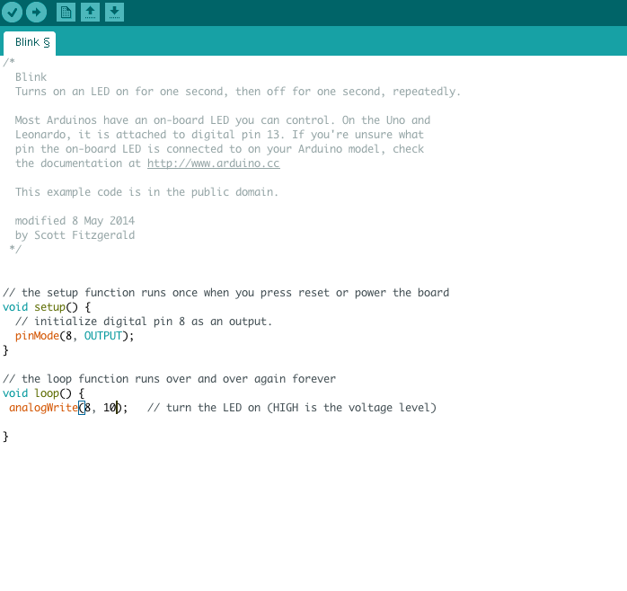
I used Arduino for programming the board, because the examples and the interface was pretty welcoming to my lack of programming skills. Under the examples, I opened the Blink file and was able to edit it so that it used the correct pin on my board that was associated with the ATTINY. Note that the pin number is different from the number to use, that is listed on the componect. So that pin 5 was really Pin 8 to use in the code.
Programming the Board
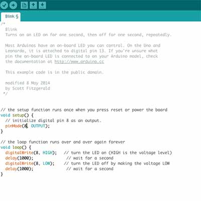
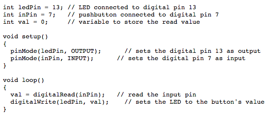
After editing the code a little, I was finally able to make my LED Blink. This was really, really exciting for me. Finally!
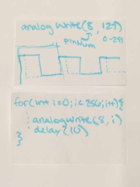
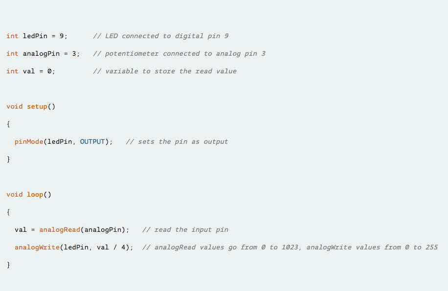
After I got that, Amanda encouraged me to keep going and she explained some really great stuff I could do with using 'for loops' and 'analog write'. Essentially, these commands would allow for subtle applications of the LED, for example, controlling the luminosity/dimmness of the light and dimming/fading in and out. In order to control the brightness of the light, I was able to rewrite the code using Analog Write, so that I was controlling the frequencey of the output of the light. Basically, by adding a value between 0-256 you can specify the duration at which the light is on and off, but all to an effect that is not noticable to the eye. This means that the amount of light perceived can be changed and so the light appears dimmer or brighter. I was able to use this code to create various levels of brightness on my LED. Additionally, in order to dim the light, bringing it down and then gradually bright again, I was able to write a code that utilized loops in order to gradually decrease brightness thrught the analog write function. Big thanks to Amanda. Hope to continue on this more...I am thinking that the FabISP was connected wrong so will go back and use it again to try and program.
Design Files
PCB Schematicterm py
echo C
echo C HEX
echo C MAKE
echo OUT