Kim Smith
Final Project
what does it do?
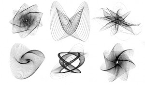
This project is a heart rate-controlled harmonograph. Harmonographs are drawing machines that use pendulums to create a geometric image. This project uses two users' heart beats to control two of the lateral arms, so that the result is a drawing composed of the intersection between their heart beats. There are two Pulsesensors connected to two corresponding unipolar stepper motors that rotate two steps clockwise, then counter-clockwise, in the cadence of the heart rate. There is a third orbital pendulum that rotate s the drawing surface to add additional axis and complexity.
who's done what beforehand?
The harmonograph was supposedly first created by Hugh Blackburn in the late 1800s. From then on, others have made variations and have used them to create Lissajous curves. In recent years, there is an interest in drawing machines and contemporary artists have experimented with the harmonograph concept. Eske Rex is know for two-axis pendulum drawings that span the whole room and use giant heavily-weighted pendulums that swing close to the floor.
what did you design?
I designed the structure of the machine, based on references from other harmonographs. I added the motor to the design so eliminated two pendulums and replaced them with a light-weight arm configuration. I designed the unipolar stepper motor circuit boards. I also designed the mold for the weights that rest on the orbital pendulum, although that was pretty simple.
what materials and components were used? where did they come from? how much did they cost?
- Materials
- 4ft x 4ft birch, 3/4 in, found/donated, typically $25
- wood glue, hardware store, $5
- screws, $2
- balsa wood, found/donated, typically $3 in art supply stores
- rubberbands, $1 from drugstore
- thin plywood for drawing board, found scrap/donated
- 9V batteries, hardware store, $6 each
- wire connectors, Amazon, $5
- copper board, class supply, $2
- Atmega 328, class supply, found at Atmel, $2.50
- n mosfet, class supply
- 8 mHz resonator, found at Digikey, $0.19
- gaffer's tape, found at art supply, $10
- drawing paper, found/donated
- misc. pens, markers
- blue foam, 2in thick, class supply
- hydrostone, class supply, found on usg.com
- misc. clips
- Pulsesensor, from PulseSensor, $15, borrowed
- unipolar stepper motors, from Jameco, $9
what parts and systems were made?
I made the machine structure, the arms, the drawing board, the orbital pendulum, the weights, the fabduino microcontrollor board, 2 unipolar stepper motor circuit boards.
what processes were used?
Designing in Rhino, Illustrator, and PartWorks. cnc Milling with Shopbot. Designing circuits in Eagle, milling copper boards on Modela, stuffing the boards/soldering, programming in C, programming in Arduino, casting with hydrostone from foam mold, basic construction
what questions were answered?
Can I actually do this?
how was it evaluated?
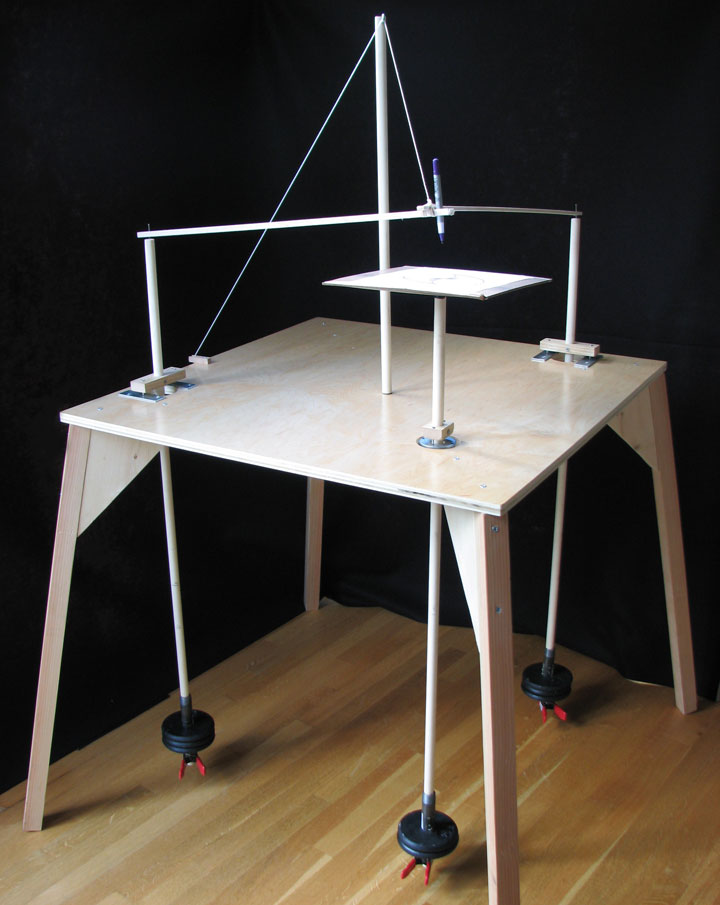
As I write this I am still having difficulty getting it to "work"...but I came a really long way and have finally put together everything and realized how much I learned. I evaluate this project from a technical standpoint in its ability to simply take input an then output and to do so within a beautiful well-designed structure.
what are the implications?
I would like to continue this piece and refine it to more closesly represent actual data. I think that it has potential to be a compelling art piece with basic technology.
Process
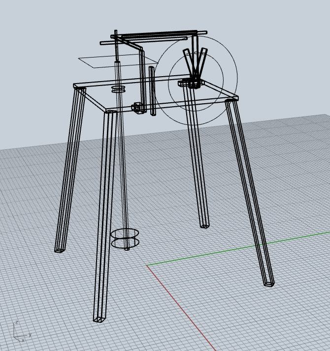
Working in Rhino was much easier and I was able to envision what I wanted. Made the model and figured my dimensions. I opted to include a third axis, which would be the orbital pendulum. I feared that without it I would not get compelling results in the drawing. So it will be two lateral axis controlled by a stepper motor that receives data from a heart rate sensor. And then under the picture plane will be the orbital pendulum. I will create the desk/frame from some extra wood I have, 3/4 in birch. The arms will be light, probably balsa.
References
Output Device
To control the arms' lateral movement, I will use a bipolar stepper motor, so that I can control its movement smoothly and precise. It will probably rotate about 30 degrees, 2 values that correspond to the high point of the heart beat. Still need to figure this out...I designed a board for the stepper motor with 2 H bridges to control it. I will attach this to a microcontroller. I milled the boards using the SDM machine and it gave me beautiful results.
I used this reference
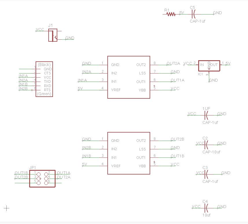
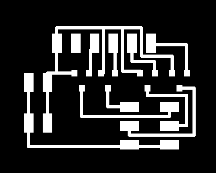
Here are my board design files, in Eagle:
Eagle SchematicEagle Board
Traces PNG
Outline PNG
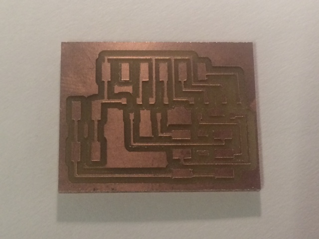
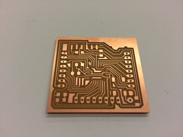
Milling the Board
I used the Modella and this time and the traces came out very well.
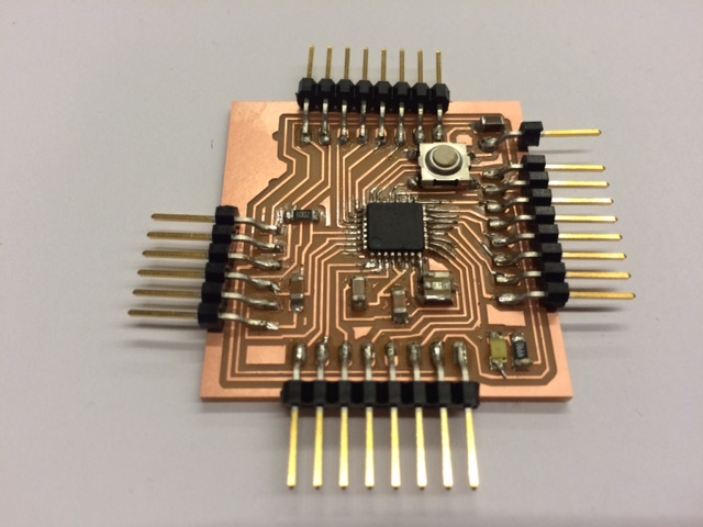
Stuffing the Board
Soldering has become much easier; still I did change out a piece and have to desolder a component. Also, after I milled and stuffed 2 boards, I went to the TA session and realized that I was missing one ground connection. Luckily it was an easy fix, so just a wire soldered on top to connect.

Making Something Big
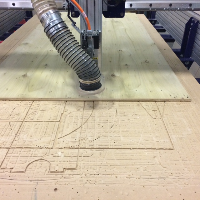
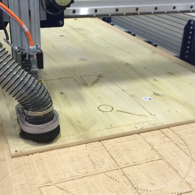
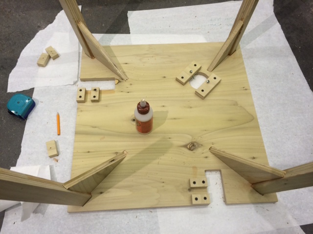
I used the ShopBot to cut my birch pieces. Pretty straightforward. Material I used was 3/4in birch, 4x4 ft. I started with a Rhino file for my design, and then exported the shapes to a 2D layout in Illustrator. I used a .125 endmill, and used multiple toolpaths to break up the cutting process. I screwed the birch down on the corners, and then used a hole toolpath to create additional holes in the design so that I could drill into the center of the wood in several places. This really helped secure a flat surface. After the holes toolpaths, I re-zeroed the axis because it was no longer bowed in the center.
The next toolpath was a pocket path, for four pockets on the underside of my table. Adding these pockets will make it more secure and allow for precise placement of the table legs.
Next was the first round of profile cuts for all the pieces. At first, I used 2 tabs for each piece; however, on the long leg pieces, the cut piece did not stay secure, and the machine caught it, messing up one of my legs. So I recreated the leg on the design, and redid the tool path to include 3 tabs on each piece, at .15in. thickness. This really helped and the rest of the cutting turned out beautifully. Still, there was some sanding to do, as well as some slight sanding in order to fit the pieces together.
After sanding, I glued the leg pieces together, so each leg will be two pieces glued together in order to create 1.5in square legs.
I clamped and let the glue sit overnight.
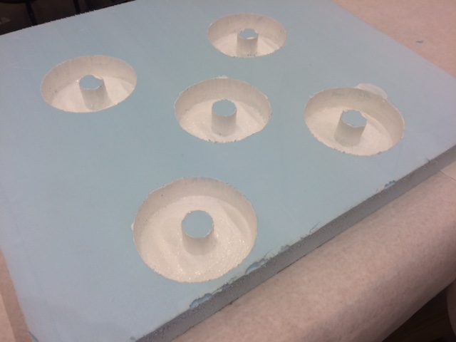
For the weight on the orbital pendulum, I casted a simple design in hydrostone, aiming for around 1 lbs for each weight. I made a simple design in Rhino and then milled a desing for the mold with the negative shape. I used a .25 in round endmill and only a roughing path. After the milling, I gessoed the mold, then covered it with finishing wax as a release agent. I poured the hydrostone and let it sit for a day.
Input Device
The input device was tricky. I relied on a PulseSensor to run on my fabdruino; however, I was unable to program my fabdruino with the Arduino library, so I opted to connect the PulseSensor to an Arduino board, which was then connected to my Atmega. I set output pins on the artduino and then connected them to pins on my atmega. The code takes the input from the pulsensors to affect the stepper motors.
I made a Fabuino board and used two Ports for the motors, one for each arm.
Stuffing the Fabduino
Toughest part was soldering the microcontroller, I used the Atmega 168, small traces! Post milling, I realized there was one spot that was coming off the board, but was able to secure a tiny pad of copper vinyl to repair it.
Programming was pretty straightforward. With some help, I adapted Neil's C code for the half stepper motor and then used the arduino library to program the pulsesensor. After everything was programmed, I hooked it up and it wasn't working. Seemed to be a software issue so I took everything apart and tried to figure out my problem. There was some issues with the communication between the boards.
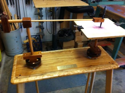
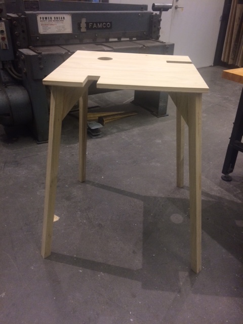
Assembly
Design Files
Rhino DesignWeights mold DXF
Eagle Schematic
Eagle Board
Traces PNG
Outline PNG
Weights mold DXF
Stepper Motor Code