Maroula Bacharidou
MAS.863 | How to Make (almost) Anything
Qubricks
1. Project description2. Whats, whys, hows and whos
3. How to Qubricks / Integration of skills
___a. Computer-aided design
___b. 3d printing
___c. Electronics design & production
___d. Embedded programming, output devices, networking & communications
___e. Interface design & programming
___f. Bringing things together
1. Project description
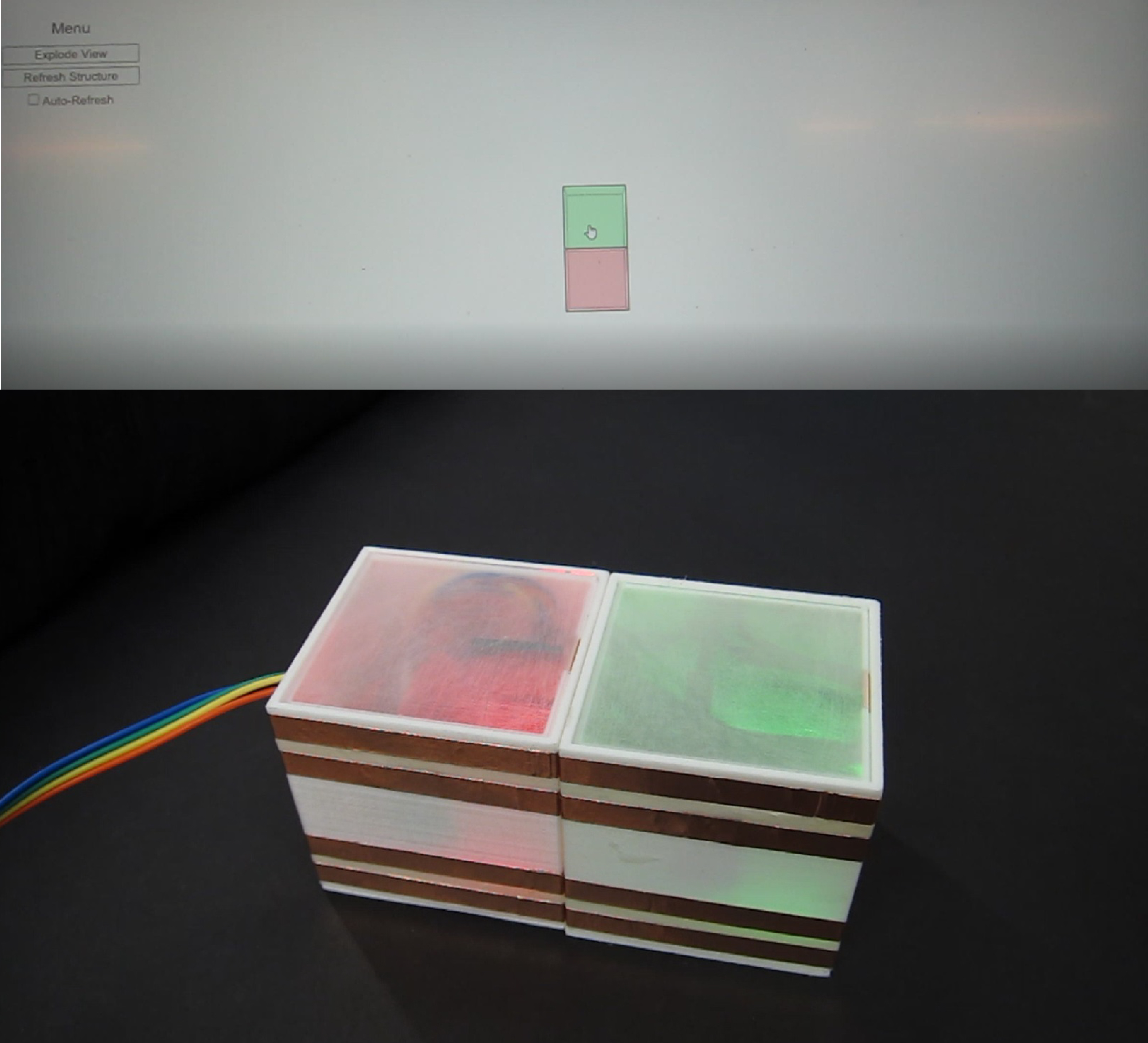
Figure 1. Qubrick's final prototype.
For my final project I made Qubricks, a making kit that brings together two different design processes, that of hands-on experimentation and that of experimentation through the use of 3D modeling software. As physical objects, they are bricks that attach with each other through magnets that are placed in the internal surfaces of their four sides. Each brick contains a central programmable microcontroller that allows the identification of its position and state, in terms of connectivity and spatial configurability, within the physical model. The pins of the microcontroller are connected to conductive pads on the external surfaces of the bricks; these pads power a microcontroller inside every brick by transfering electricity from a central power source through adjacent bricks; they also serve as datalines for the communication of neighboring microcontrollers. Each brick can identify its position by querying its neighbor ids and inform a central computer about it by passing messages in the network through serial communication. The central computer collects data from multiple bricks tracking the construction process piece by piece. It can also send custom commands to each brick to control its color which changes using an internal RGB LED. The LEDs can serve as indicators that guide a user during the reconstruction process of a particular design but they can also be integral parts of the design itself. The inputs and outputs created within the model are visualized via an node.js application that gets their spatial configurations in a 2-dimensional environment and creates an .svg drawing in the screen of the computer.
Video 1. Two Qubrick prototypes interacting.
2. Whats, hows and whos
- Who's done what beforehand?
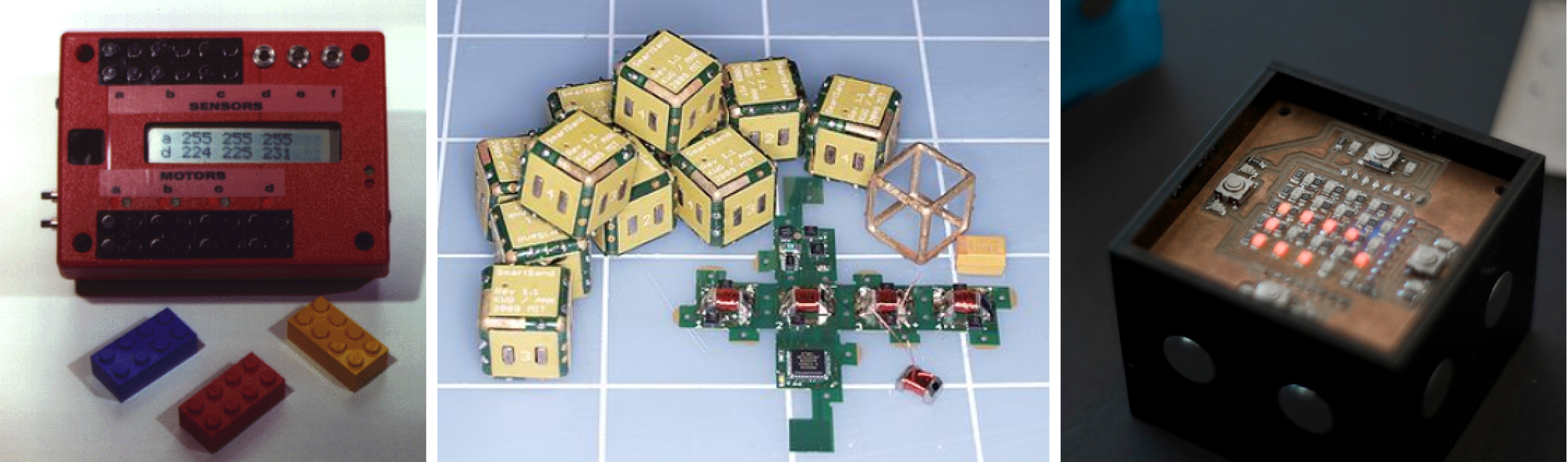
Figure 2. Mitchel Resnick's programmable brick, Kyle Gilpin's and Daniela Rus's Self-Disassembling Robot Pebbles, Dimitris Papanikolaou BlockNet.
The idea of programmable bricks has been developed by many researchers and designers inside and outside MIT. Relevant to Qubricks work that has been done beforehand includes:
- Mitchel Resnick's programmable brick,
- Kyle Gilpin's and Daniela Rus's Self-Disassembling Robot Pebbles,
- Dimitris Papanikolaou BlockNet.
- what materials, components and tools were used, and how much did they cost?
For the fabrication of my brick prototype, I used materials, tools and machines mostly provided by the fab lab inventory.
Each prototype consisted of:
- 3d printed shells for the bricks (I used my school studio's Makerbot and Hatchbox 1.75 mm white PLA filament),
- neodmium magnets (I used Magnet Source 07046 0.47-Inch Neodymium Magnet Discs, Pack of 6, cost = $9.94 per pack - I bought two packs),
- a pcb that I made (stuffed with an ATTiny 44a, an RGB LED, resistors and ceramic capacitors from the Architecture shop),
- female to female jumpers (Adafruit's 3" Female To Female Jumper Wires - Pack Of 40 Wires, cost = $4.73 per pack, two packs)
- copper conductive adhesive tape from the Architecture shop
- FTDI cable (I used SparkFun's one, cost = $ 17.95),
,
- AVR ISP to program my boards
3. How to Qubricks / Integration of skills
For my final project I had the opportunity to use a lot of the topics that we covered throughout the semester: computer-aided design and 3d printing (for the bricks); computer controlled cutting (for the kit base and the semi-translucent parts of the bricks); embedded programming and output devices (for the RGB LED and the PCB programming); networking (for the communication and the connections among the bricks); interfaces and applications (for the visualization of the configurations of the bricks).
___a. Computer-aided design & computer-controlled cutting
The design of my bricks ended up being much simpler than the one that I had proposed in week 1, however I had to consider a lot of parameters this time (Fig. 3):
- the size of the copper conductive strips (6 mm) each,
- the diameter of the magnet (1.27 mm), which I did not want to involve in my electronics part (I will definitely do it in a future project), so I had to keep it untouched by the copper pads
- the size of my pcb (31.5 x 37.5 mm), which I wanted to press-fit in a socket in the 3d-printed brick bottom.
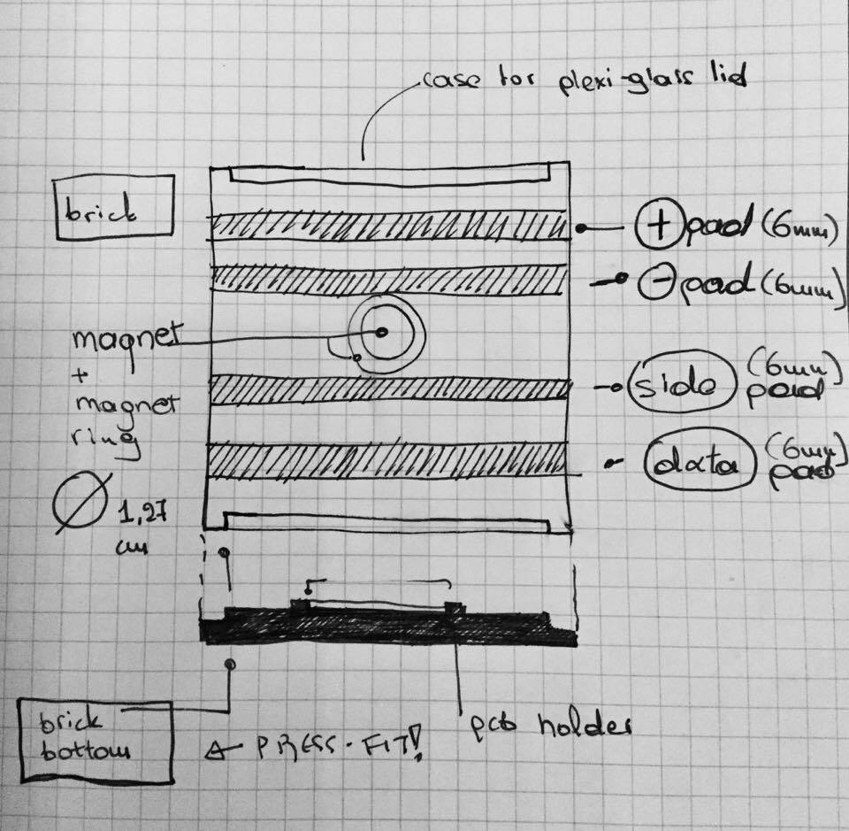
Figure 3. Sketching my model and considering the variousparameters before finally modeling it.
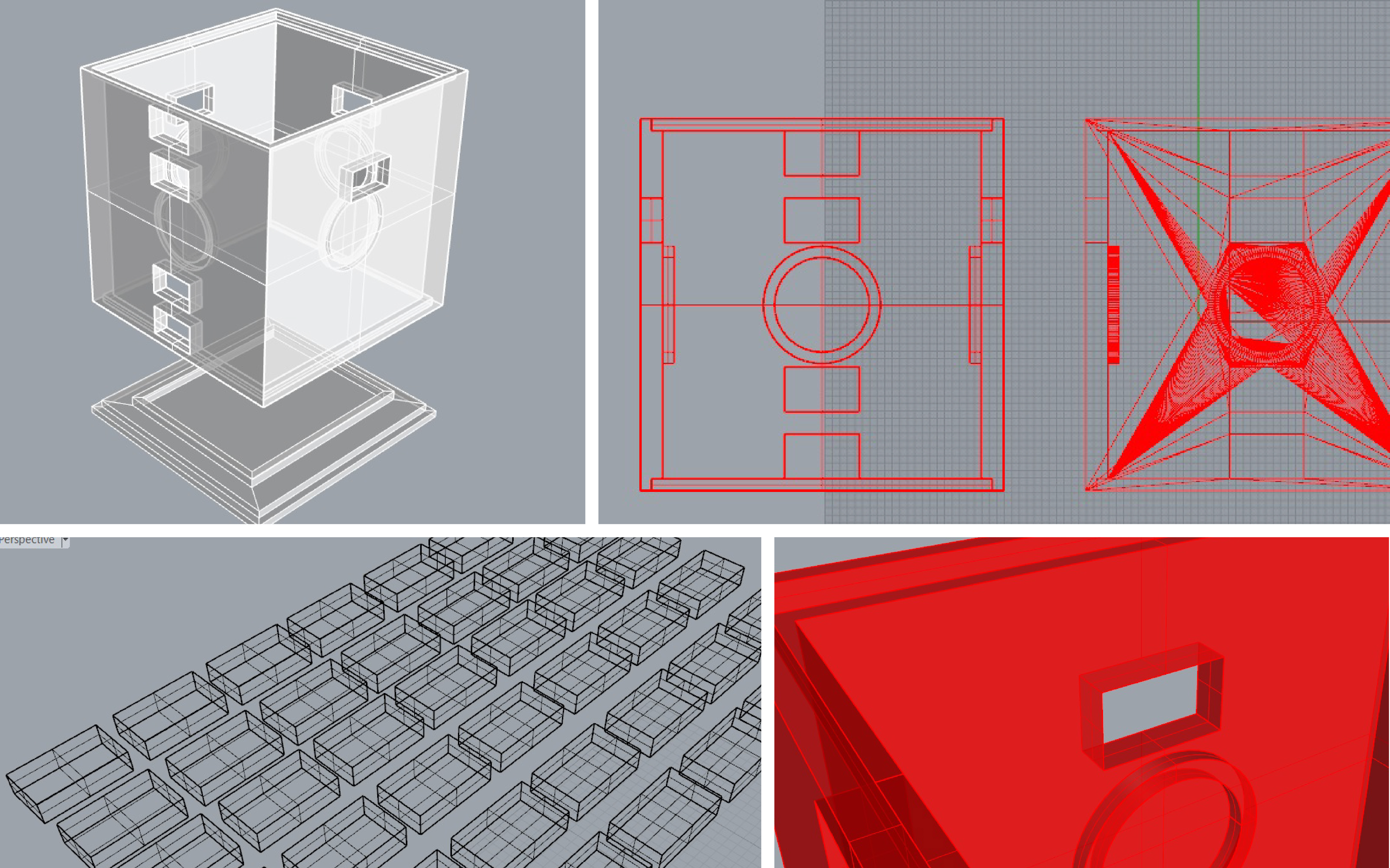
Figure 4. Designing my model in Rhinoceros; apart from the brick shells, I designed the 3d printed pads that were later covered with the adhesive copper tape so that they would be conductive.
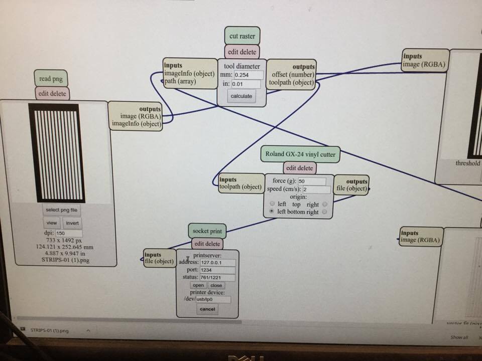
Figure 5. Sending my .png files of the conductive pads and strips to the Roland vinyl cutter.
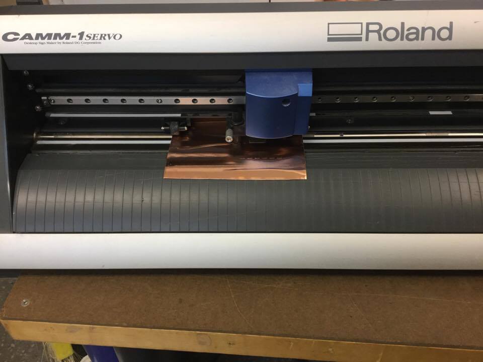
Figure 6. Vinyl-cutting the pads and the strips.
___b. 3d printing
After modeling my brick, its bottom and its pads, I used the MakerBot software to prepare it. I used the "High" presets, which meant a fair amount of printing time - but exceptionally good quality and precision, as I realized after, for such a cheap machine. Using raft when printing "empty" objects proved extremely important, as without it the freshly extruded material can not get stabilized in the position that it should be extruded . I did not use any support materials as the software indicated that they were not needed - the extrusion speed was slow enough to allow that!
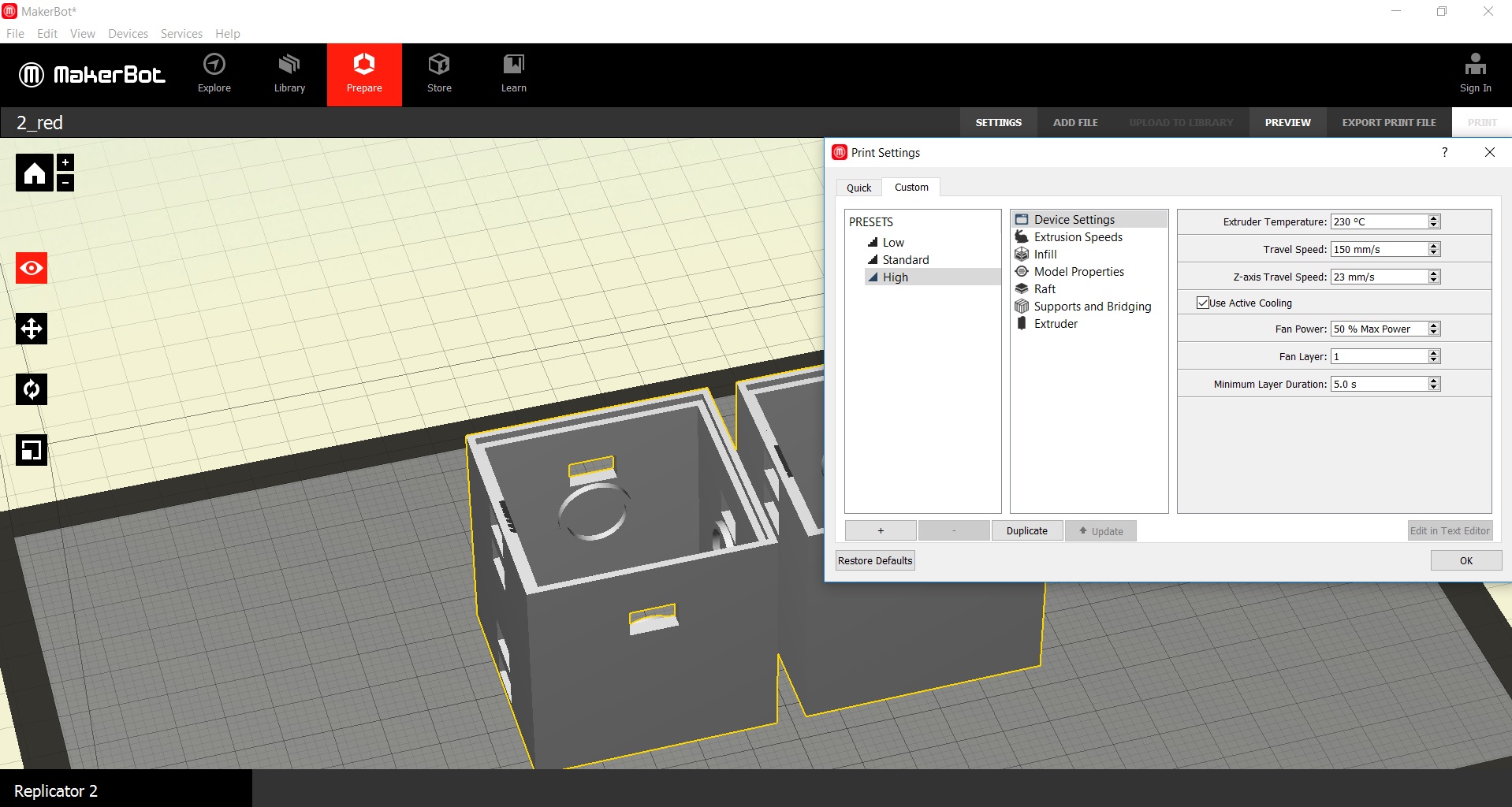
Figure 7. Preparing my model in the MakerBot software.
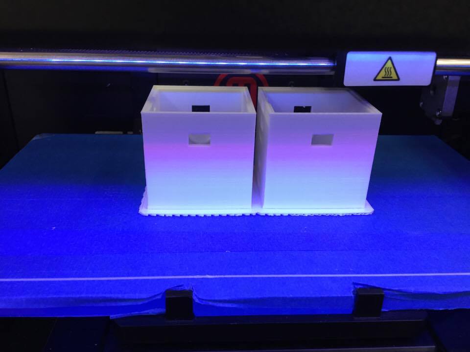
Figure 8. Watching my model being printed in the Architecture studio's MakerBot. Using raft really helped to get these hollow rectangles in the right shape!
___c. Electronics design & production
For the electronics part I used the board that I designed and made during week 10. I solved the rainbow cable issue that I had (the two holders did notfit on my milled board next to each other) by using female-to-female jumper cables. One advantage of jumper cables compared to the nake-edged wires of the rainbow cable was that i could make more stable connections with the conductive copper pads by soldering pins to the latter. Despite that I needed only 4 + 4 pins out of the 6 + 6 that I used for the final design of my board, I wanted to have more "free" pins to test my project out of the bricks - that meant more cables (+, -, data, "sides") = more pins!
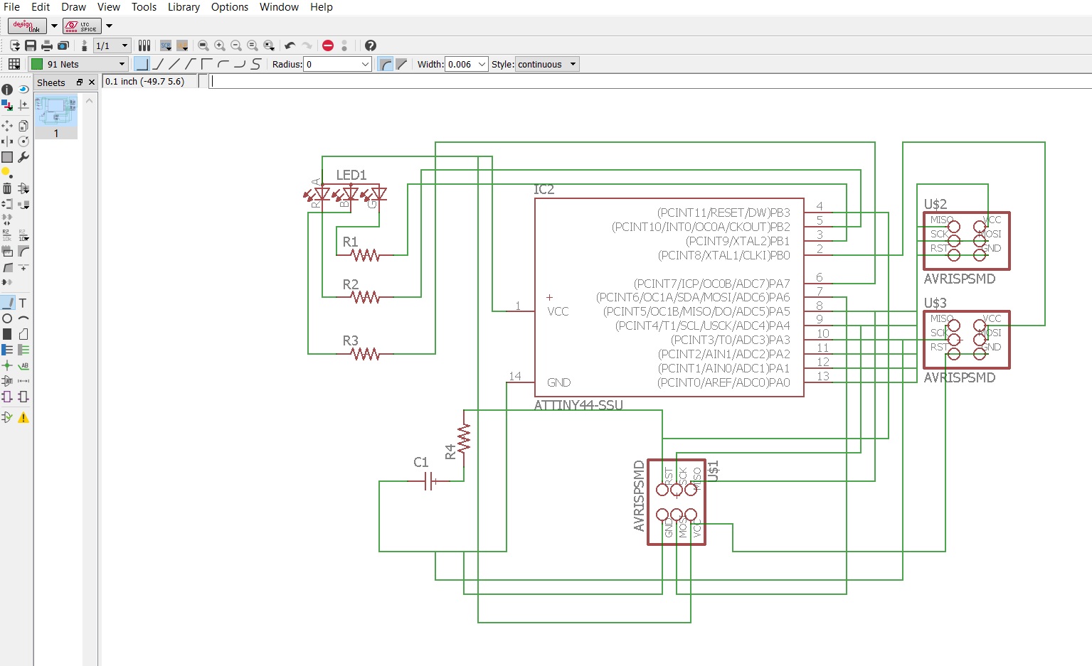
Figure 9. Collecting my board parts from fab-lbr in EAGLE and making my connections in the schematic mode.
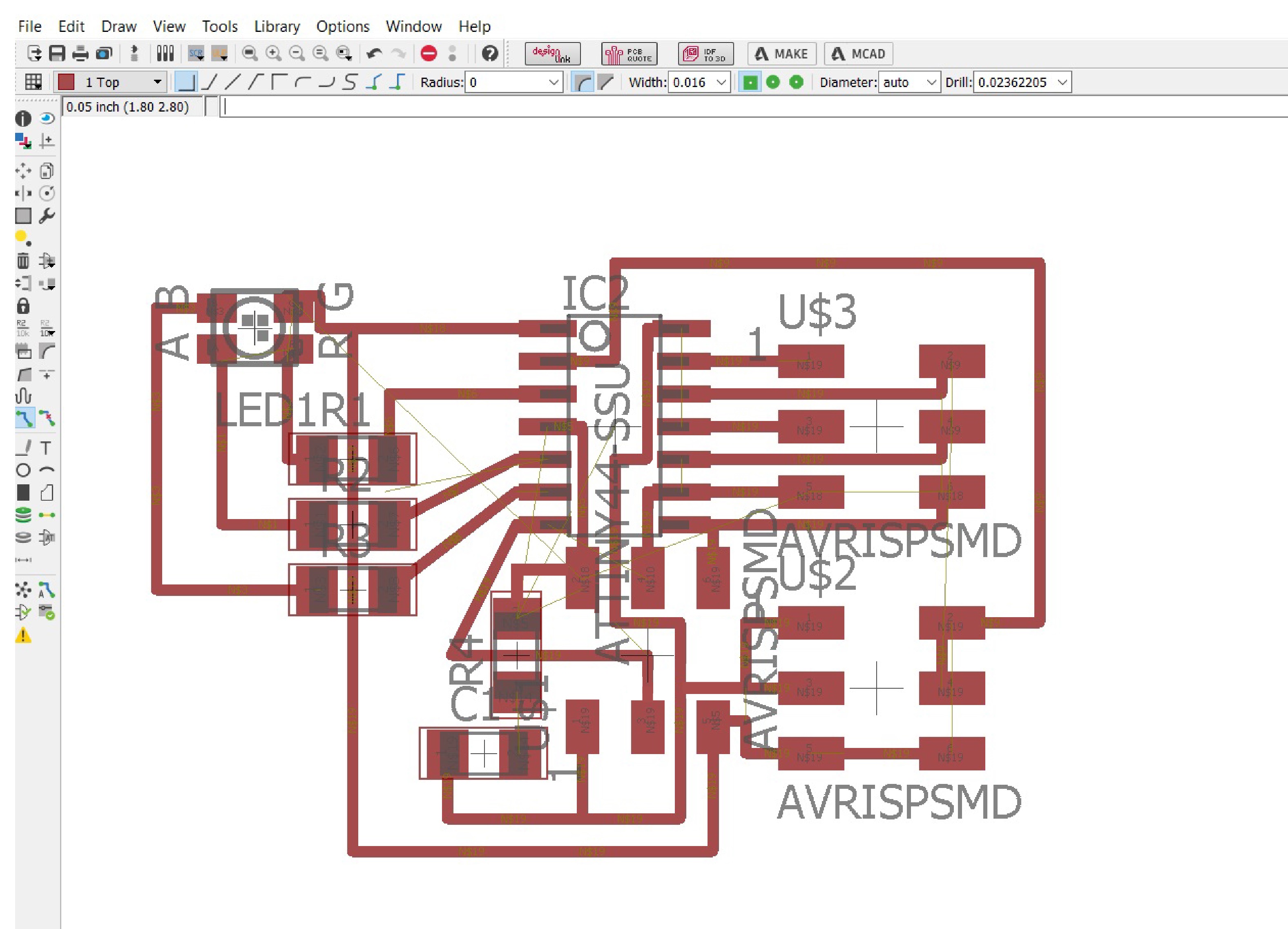
Figure 10. Routing was "tight" in some parts of the board, especially the one around the bottom ISP.
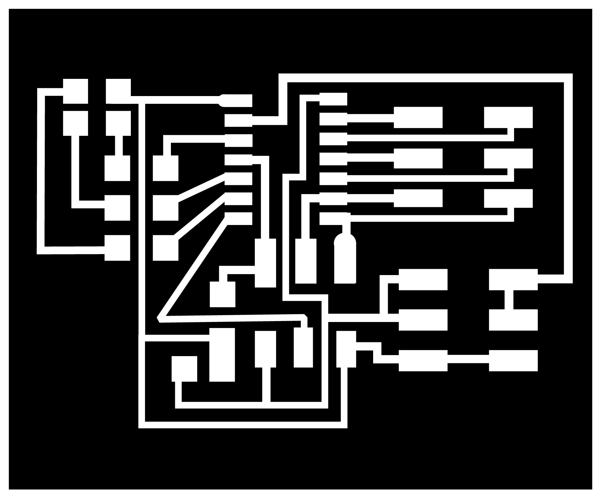
Figure 11. The final design of my board.
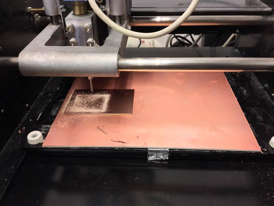
Figure 12. Milling the board in the Roland Modela.
___d. Embedded programming, output devices, networking & communications
Programming the boards to power an output device while interacting with each other meant that I had to combine embedded programming, output devices and networking and communications programming in the code that my boards would run. I programmed my board in C, reading a lot, getting a lot of coding advice, and learning a lot! That was one of the most challenging parts of my project development that I was working for from networking and communications week and I'm glad that it worked now. Here the biggest question that I had from the start of the semester was answered: how can my bricks can identify their positions by querying its neighbors ids, and inform the central computer about it? The code I wrote is the same for all the processors, master and slaves. The ID = 0 condition applies only to the master so every other ID belongs to a slave processor.
#define ID 3
#include "common.h"

static unsigned char graph[53];
static unsigned char neighbors[4] = {0,2,3,4};

void handle_packet();

void handle_led() {
  int id = packet.header & 15;
  if(ID == 0) put_packet();
  if(id != ID && id != 0xf) return;
  int value = packet.row1;
  for(int i=0;i<3;i++) write(*led_ports[i], led_pins[i], value!=i+1);
}

void handle_get_graph() {
  if(ID != 0) return;
  packet.header = (FORGET_NEIGHBORS<<4) | 0xf;
  packet.checksum = 0;
  handle_packet();

  for(int i=0;i<10;i++) {
    packet.header = (INFORM_NEIGHBORS<<4) | i;
    packet.checksum = 0;
    handle_packet();
    if(i>0) get_packet_nonblocking();
  }

  for(int i=0;i<4;i++) {
    put_char(&serial_direction, &serial_port, serial_out, to_hex( neighbors[i] ) );
  }
  for(int i=1;i<10;i++) {
    packet.header = (GET_NEIGHBORS_LIST<<4) | i;
    packet.checksum = 0;
    put_packet();
    get_packet_nonblocking();

    if(!packet.checksum) {
      put_char(&serial_direction, &serial_port, serial_out, '|' );
      put_char(&serial_direction, &serial_port, serial_out, to_hex(packet.row1>>4) );
      put_char(&serial_direction, &serial_port, serial_out, to_hex(packet.row1&15) );
      put_char(&serial_direction, &serial_port, serial_out, to_hex(packet.row2>>4) );
      put_char(&serial_direction, &serial_port, serial_out, to_hex(packet.row2&15) );
    } else {
      put_char(&serial_direction, &serial_port, serial_out, '|' );
      put_char(&serial_direction, &serial_port, serial_out, to_hex(i&15) );
      put_char(&serial_direction, &serial_port, serial_out, to_hex(i&15) );
      put_char(&serial_direction, &serial_port, serial_out, to_hex(i&15) );
      put_char(&serial_direction, &serial_port, serial_out, to_hex(i&15) );
    }
  }
  put_char(&serial_direction, &serial_port, serial_out, '\r' );
  put_char(&serial_direction, &serial_port, serial_out, '\n' );
  put_serial_string(graph);
}

void handle_forget_neighbors() {
  int id = packet.header & 15;
  if(ID == 0) put_packet();
  if(id != ID && id != 0xf) return;
  for(int i=0;i<4;i++) neighbors[i] = ID;
}

void handle_inform_neighbors() {
  int id = packet.header & 15;
  if(ID == 0) put_packet();
  if(id == ID) {
    //DDRA |= pins_bitmap;
    //PORTA &= ~pins_bitmap;

    for(int i=0;i<4;i++) set(DDRA,pins[i]);
    for(int i=0;i<4;i++) clear(PORTA,pins[i]);

    bit_delay(); bit_delay(); bit_delay();
    bit_delay(); bit_delay(); bit_delay();
    bit_delay(); bit_delay(); bit_delay();
    bit_delay(); bit_delay(); bit_delay();
    bit_delay(); bit_delay(); bit_delay();

    for(int i=0;i<4;i++) clear(DDRA,pins[i]);
    for(int i=0;i<4;i++) set(PORTA,pins[i]);

    //DDRA &= ~pins_bitmap;
    //PORTA |= pins_bitmap;

    packet.header = (INFORM_NEIGHBORS_RESPONSE<<4) | ID;
    packet.checksum = 0;
    put_packet();
  } else {
    bit_delay(); bit_delay(); bit_delay();
    bit_delay(); bit_delay(); bit_delay();
    for(int i=0;i<4;i++) if(!pin_test(PINA,pins[i])) neighbors[i] = id;
  }
}

void handle_get_neighbors_list() {
  int id = packet.header & 15;
  if(ID == 0) put_packet();
  if(id != ID) return;

  packet.header = (GET_NEIGHBORS_LIST_RESPONSE<<4)|ID;
  packet.row1 = ((neighbors[0]<<4)|neighbors[1]) & 0xff;
  packet.row2 = ((neighbors[2]<<4)|neighbors[3]) & 0xff;
  packet.checksum = 0;

  put_packet();
}

void handle_packet() {
  if(packet.checksum) return;
  switch(packet.header>>4) {
    case LED: handle_led(); break;
    case GET_GRAPH: handle_get_graph(); break;
    case FORGET_NEIGHBORS: handle_forget_neighbors(); break;
    case INFORM_NEIGHBORS: handle_inform_neighbors(); break;
    case GET_NEIGHBORS_LIST: handle_get_neighbors_list(); break;
  }
}

void setup() {
  // put your setup code here, to run once:
  CLKPR = (1 << CLKPCE);
  CLKPR = (0 << CLKPS3) | (0 << CLKPS2) | (0 << CLKPS1) | (0 << CLKPS0);
  set(data_port, data_pin);
  for(int i=0;i<4;i++) set(PORTA, pins[i]);
  set(serial_port, serial_out);
  for(int i=0;i<3;i++) set(*led_directions[i], led_pins[i]);
  for(int i=0;i<3;i++) set(*led_ports[i], led_pins[i]);
}

void loop() {
  // put your main code here, to run repeatedly:
    if(ID==0) get_serial_packet();
    else get_packet();
    handle_packet();
}
___e. Interface design & programming
This was another part of the project that became possible thanks to a weekly assignment, that done in interface and application programming week. Here is the code that I wrote (again, reading, failing, asking, learning) to make the serial communication between the different processors possible. After initiating the serial communication, the node.js code (attached on the interface and application programming) generates an. svg image of the configurations between the different pins of the processor -and therefore, sides of the bricks-. The user can switch the LEDs through the application. The application operates through an .html page that calls the main.js script and generates the switchable .svg image. (the code for these parts is long and can be found in my networking and communications page)
var io = require('socket.io')(8080);
var SerialPort = require('serialport');

var port = new SerialPort('COM6', {
  baudRate: 9600,
  parser: SerialPort.parsers.readline()
});

port.on('data', function (data) {
  console.log('Data: ' + data);
  io.emit('message', data.trim());
});

io.on('connection',function(socket) {
  console.log('connected');
  socket.on('led', function(data) {
    var id = data.id|0;
    var state = data.state|0;
    var bytes = Buffer.from([0x10^id, state, 0, 0x10^0x9d^state^id]);
    console.log(bytes);
    port.write(bytes);
  });
  socket.on('refresh', function() {
    var bytes = Buffer.from([0x20, 0, 0, 0x20^0x9d]);
    //console.log(bytes);
    port.write(bytes);
    //test();
  });
});

function rotate( array , times ){
  while( times-- ){
    var temp = array.shift();
    array.push( temp )
  }
}

//test
function test() {
  var A = [
    [-1,-1,-1,-1,-1,-1],
    [-1,-1,-1,-1,-1,-1],
    [-1,-1,-1,-1,-1,-1],
    [-1,-1,-1,-1,-1,-1],
    [-1,-1,-1,-1,-1,-1],
    [-1,-1,-1,-1,-1,-1],
  ];
  for(var i=0;i<10;i++) {
    while(1) {
      var x = Math.ceil( Math.random() * 4 );
      var y = Math.ceil( Math.random() * 4 );
      if(A[x][y]==-1) {
        A[x][y] = i;
        break;
      }
    }
  }
  console.log(A);
  var msg = [];
  for(var i in A) {
    for(var j in A[i]) {
      if(A[i][j] < 0) continue;
      var n = [ A[i-1][j],A[i][j*1+1],A[i*1+1][j],A[i][j-1] ];
      for(var k=0;k<n.length;k++) if(n[k]<0) n[k] = A[i][j];
      rotate(n, Math.floor( Math.random() ) );
      msg[A[i][j] ] = n.join('');
    }
  }

  console.log( msg.join('|'));
  io.emit('message', msg.join('|'));
}

//setInterval(test,2000);
Video 2. Making and visualizing connections between the boards.
___f. Bringing things together
After designing and fabricating the parts of my bricks, making the pcbs and programming them, the "bringing things together" part of the process came about. Everything that I worked for during the previous part would just not work if things were not put together in the right way. This process involved a lot of hands-on training and experimentation - training on handling wires gently and experimentation on finding the right angles for soldering pins to pads, braiding jumpers, sanding 3d printed parts. Some important parts of this process were enjoyable and, at some moments, were painful (the neodmium magnets kept jumping off their sockets and pinching me). The multimeter, throughout this long process, was my only and best friend.